
Instruments · Marine chronometer
Marine chronometer by Edward Thomas Loseby
- Maker / attribution
- Edward Thomas Loseby (Made by); Caffin (Movement made by (attributed)); Cattin (Movement made by (attributed)); Cotton (Movement made by (attributed))
- Date
- 1845–1853
- Historical period
- Precision & Scientific Horology (1750 – 1850)
- Country of origin
- England
- Place
- London (England)
- Object type
- Marine chronometer
- Materials / technique
- mahogany, brass, mercury
- Holding institution
- British Museum
- Accession / object no.
- 1958,1006.1933
- Credit line
- British Museum, London
- Catalogue title (original)
- Marine chronometer by Edward Thomas Loseby (English)
View the source record ↗ (opens another website in a new tab)Suggest a correction
Record summary
Held and catalogued by British Museum (object number 1958,1006.1933), this is a marine chronometer by Edward Thomas Loseby, made in London (England), dated 1845–1853. The Atlas places it in the Precision & Scientific Horology period (1750 – 1850) of its Instruments collection. Materials and techniques recorded by the source: mahogany, brass, mercury. The record is illustrated with 3 photographs.
Assembled from the source record's structured fields. Dates and attributions are given as the source states them; where a field is missing the Atlas leaves it blank rather than estimating.
Catalogue description
Description — British Museum
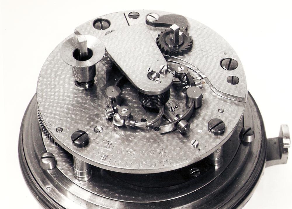
Marine chronometer; Earnshaw spring detent escapement; movement in brass bowl gimballed in brass-bound mahogany box; silvered flat engraved brass dial, engraving filled with black wax; gold minute and hour hands, blued steel seconds and up-and-down hands.
Curator's comments — British Museum
Comment from Anthony G. Randall and Richard Good, Catalogue of Watches in the British Museum. Vol. VI (1990) Made by Edward Thomas Loseby (1817-1890), c. 1850 Marine Chronometer Signature: On the back plate 'Loseby London'. On the dial 'Loseby London 126'.(l) Box: The movement contained in a brass bowl, the front bezel with a flat glass, gimballed in a brass-bound mahogany box. The box is fitted with the usual lock, carrying handles and a glazed panel in the top under a hinged lid. It is in mint condition but for the loss of the inset ivory disc in the front of the top. There is a numbered tipsy key. Box 161.5 mm square, h. 174 mm. Dial and hands: Silvered flat engraved brass dial, the engraving filled with black wax, secured by two screws in a recess in the dial plate. The hour hand makes a revolution in 24 hours and the dial is engraved accordingly. Gold minute and hour hands, blued steel seconds and up-and-down hands. Movement: The frame parts numbered 126. Dial plate diam. 91.4 mm; front plate diam. 76.5 mm; back plate diam. 76.7 mm; frame h. 22.0 mm. Frame: Typical full plate construction with a detachable barrel bridge, four turned pillars, the back plate retained by blued steel screws. The dial plate a thick turned ring of brass, with the front plate fitting into a recess and held by three brass screws in the dial plate. The brass parts are hand spotted. Fusee: Fitted with the usual stop-work and maintaining power. A large dust-excluding cap is fitted on the winding square, and the setting-up-work is on the barrel bridge. The well-made mainspring is solid hooked to the barrel wall, the arbor is unsnailed and made from the solid. The signature on the mainspring is almost illegible, it could be 'Cattin', 'Caffin' or 'Cotton'. Going train: Well made and finished, the brass wheels polished flat on both sides, the pinions and arbors polished to the usual high standard of English chronometer work of the period. Jewelling: The fourth pivot on the dial side, and those of the escapement, in pierced jewels, the escapement with end-stones. A diamond endstone in a blued steel setting in the balance cock. The fourth jewel is protected by a pierced cover, recessed on the inside, held in the sink with the jewel setting by two screws. This is to prevent dirt from falling through the hole in the dial for the seconds arbor, and contaminating the oil in the jewel sink. Escapement: A development of Earnshaw's spring detent escapement, and very well made throughout. The brass escape wheel with rim and arms recessed on the side towards the back plate. The steel impulse roller polished on the edge and hollow, grained on the top and bottom, and set with a radial jewel. The discharge roller polished on the edge and bottom, with an adjusting flat, and jewelled in the usual English way in a hole breaking into the edge. The detent straight and finished with a fine grain, with a gold passing spring held under a screw head. Banking is provided by the head of a brass screw set in a slotted hole in a bracket against the balance potence foot. The locking stone is triangular, and held with a brass wedge and shellac. Balance: Bimetallic two-armed balance, the steel parts blued, secured by two screws on a brass collet on the staff. The free ends of the rim sections are shorter than usual and each carries a brass bracket held by the screw on which the quarter nut is fitted. Curved mercury-filled brass tubes are cemented into holes in the brass brackets. Each tube is held by its bulb and is curved towards the balance centre. Brass compensation weights and quarter nuts are also fitted. The purpose of the mercury tubes is to cause the rate of compensation to increase with rising temperature and decrease with falling temperature. This non-linearity of compensation can be adjusted to match the non¬linear changes in elasticity of the carbon steel spring. A plain bimetallic balance and carbon steel spring has a losing rate at extremes of temperature if correct at a middle temperature. The diameters of the mercury bulbs, about 4.9 mm, do not differ by more than about 0.02 mm. Diam. of rim 29.4 mm, h. 3.6 mm. Balance spring: Blued steel helical spring of 10 turns, with terminal curves. The brass collet has a split counterpoising tail, the brass stud is held with a screw in a slot on the balance cock. It has a screw in the side to adjust its distance from the balance centre. Going-train counts: Great wheel (fusee) 90 teeth, 8½ turns of groove Centre pinion 14 leaves, wheel 90 teeth, 5 arms Third pinion 12 leaves, wheel 80 teeth, 5 arms Fourth pinion 10 leaves, wheel 80 teeth, 5 arms Escape pinion 10 leaves, wheel 15 teeth, 3 arms Beats per hour: 14,400 Motion work: Cannon pinion 14 leaves, minute pinion 10 leaves Hour wheel 60 teeth, minute wheel 56 teeth. Up-and-down work: Pinion 8 leaves, wheel 90 teeth (identical with the centre wheel) Provenance: Ilbert Collection; in his inventory notebook Ilbert states that he acquired this chronometer from Malcolm Gardner in 1942, and adds that it came from Loseby's executors.(2) Exhibited: British Watches and Clocks, City of Birmingham Museum of Science and Industry, October 1953-February 1954. Notes: (1) Edward Thomas Loseby died at Leicester in 1890. He submitted his first chronometer fitted with a balance embodying mercury in glass tubes to the Admiralty in 1843. More chronometers so fitted were tried at Greenwich in 1844 and 1845, and the Astronomer Royal, Airy, reported favourably on them. Between 1845 and 1853 Loseby obtained very good results in the trials at Greenwich, but finally became discouraged when he did not receive special financial reward for his work. He therefore retired to Leicester in 1853 where he worked as a high-class watch and clockmaker until his death (2) Malcolm Gardner in a letter to Gould dated 17 November 1948 records that this chronometer was with others in Loseby's effects at his death. Loseby had instructed his executors not to sell any of the chronom.
Inscriptions & marks
signature; back-plate; Loseby London; signature; dial; Loseby London 126; signature; mainspring; Partially illegible, Cattin, Caffin or Cotton.
Provenance
Previous owner/ex-collection:, Courtenay Adrian Ilbert, Previous owner/ex-collection:, Grimson; Donated by:, Gilbert Edgar; Acquired 1958
Historical context
Precision & Scientific Horology (1750 – 1850)
Harrison solves longitude; Mudge invents the lever; Breguet's Paris workshop defines the modern watch.
The longitude problem was solved by the marine chronometer and lunar distance methods; dividing engines made precision scales possible, and observatories set time by transit instruments.
Read the period in the timelineMore instruments from this periodEarlier: Early Modern Horology
Atlas type guide
Marine chronometers
A marine chronometer is a precision timekeeper carried at sea to find longitude: the navigator compares local noon, observed with a sextant, with the time at a reference meridian kept by the chronometer. Each hour of difference corresponds to fifteen degrees of longitude. John Harrison proved the method in the 1760s; Pierre Le Roy, Ferdinand Berthoud, John Arnold and Thomas Earnshaw then developed the detent escapement and the compensation balance that made chronometers practical to manufacture.
By the nineteenth century London, Liverpool, Le Locle and Glashütte supplied navies and merchant fleets. A typical box chronometer has a spring-detent escapement, a fusee to equalise mainspring torque, a bimetallic compensation balance with a helical balance spring, and is mounted in gimbals inside a wooden box so that it stays level.
What to look for
- Gimbals and a three-tier wooden box with a glazed inner lid.
- A power-reserve ('up and down') indicator on the dial, usually showing 56 hours on two-day instruments.
- Spring-detent escapement and a cylindrical (helical) balance spring visible through the movement.
- Admiralty or navy marks (broad arrow), and rating certificates from observatories.
- The maker's number on the dial and movement; many makers' registers survive, allowing dating.
Dating clues
- Earnshaw-type spring-detent chronometers became standard after about 1800.
- Auxiliary compensation devices on the balance appear from the mid-nineteenth century.
- Quartz and radio time signals ended routine use of mechanical chronometers in the 1970s and 1980s.
General guidance written by the Atlas editors about this kind of object. It is not a statement about this particular piece; for that, rely on the source record above and on physical examination.
Read next:Detent escapement
Related records
Instruments · 1731–1776
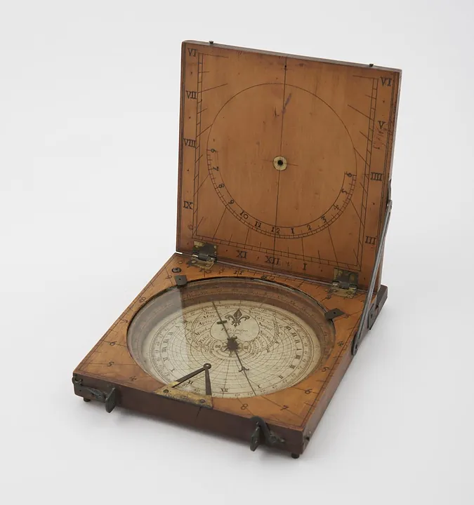
Azimuth compass sundial by James Ferguson, London, England, 1731–1776. Could also be used as a tablet sundial - string gnomon is missing (see note).
Science Museum Group, London
Instruments · 1738–1777
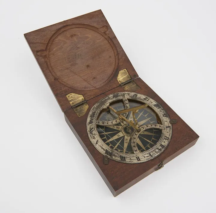
Azimuth sundial 4 3/8" diam, with folding gnomon fitted in mahogany case, made by B. Martin
Science Museum Group, London
Instruments · 1750–1800
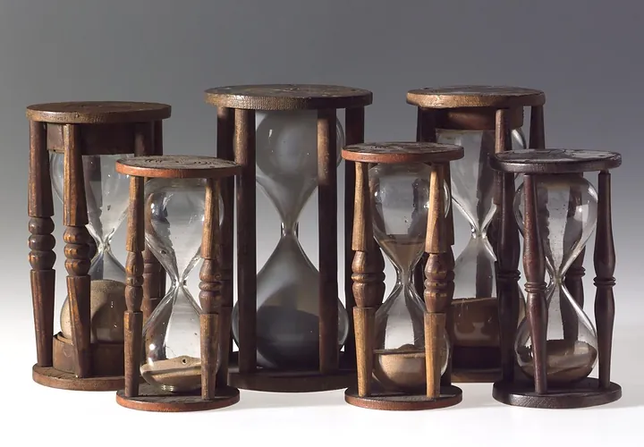
Single sand glass in four pillared wooden mount. 17 minutes. Horne Type B. Second half of the 18th century
Science Museum Group, London
Instruments · 1751–1825
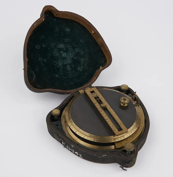
Sundial, by Troughton, in case. Invented and made by Troughton
Science Museum Group, London
Instruments · 1751–1850
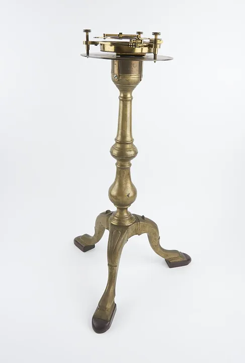
Universal Sundial; by Dollond and large brass stand, engraved "Dollond London" 6-inch hours circle, divided to 2 min, 3 levelling screws
Science Museum Group, London
Instruments · 1760–1769
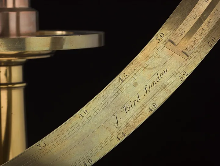
Armillary / astronomical instrument by John Bird, England, 1760–1769
Science Museum Group, London
Instruments · 1763–1829
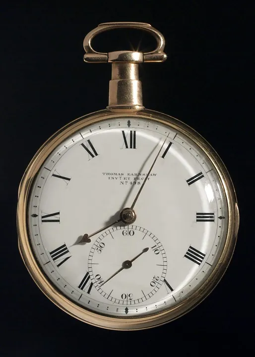
Chronometer watch by Thomas Earnshaw No.498, with later barrel cover numbered 2829, balance cock and regulator. In 18 ct. gold case hallmarked 1807/8
Science Museum Group, London
Instruments · 1770
Marine timekeeper 'H5' by John Harrison and Son, England, 1770
Science Museum Group, London