
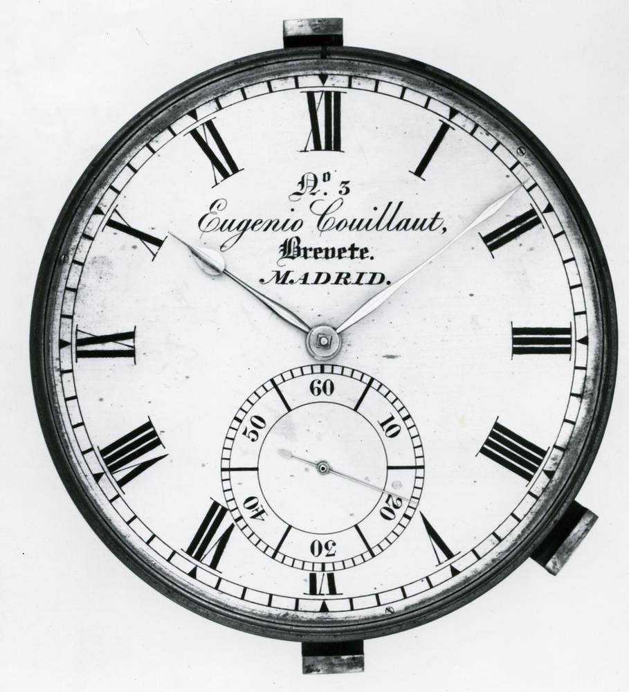
Instruments · Marine chronometer
Marine chronometer by William Hardy
- Maker / attribution
- William Hardy (Made by)
- Date
- 1800–1810
- Historical period
- Precision & Scientific Horology (1750 – 1850)
- Country of origin
- England
- Place
- London (England)
- Object type
- Marine chronometer
- Materials / technique
- mahogany
- Holding institution
- British Museum
- Accession / object no.
- 1958,1006.1958
- Credit line
- British Museum, London
- Catalogue title (original)
- Marine chronometer; small; one-day movement with Hardy's patent bar balance; circular silvered-metal dial; original mahogany box (English)
View the source record ↗ (opens another website in a new tab)Suggest a correction
Record summary
Held and catalogued by British Museum (object number 1958,1006.1958), this is a marine chronometer by William Hardy, made in London (England), dated 1800–1810. The Atlas places it in the Precision & Scientific Horology period (1750 – 1850) of its Instruments collection. Materials and techniques recorded by the source: mahogany. The record is illustrated with 6 photographs.
Assembled from the source record's structured fields. Dates and attributions are given as the source states them; where a field is missing the Atlas leaves it blank rather than estimating.
Catalogue description
Description — British Museum
Marine chronometer; small; one-day movement with Hardy's patent bar balance; circular silvered-metal dial; original mahogany box.
Curator's comments — British Museum
Comment from Anthony G. Randall and Richard Good, Catalogue of Watches in the British Museum. Vol. VI (1990) Made by William Hardy, c. 1805 Chronometer movement Signature: On the balance cock and back plate ' Wm. Hardy LONDON No. 53 Invt et Fecit'. On the dial 'W Hardy LONDON Invt. et Fecit'.(1) Box: The movement protected by a canister dust cover fixed with screws to the dial plate, and fitted in a brass drum with a threaded bezel and domed glass. The brass drum is gimballed in a mahogany box. An inset flush with the upper edge of the bottom part of the box has a large central hole for the gimbal ring, with two brass brackets in opposite corners for the pivoting screws, and a third bracket for the locking device fitted on top of the gimbal ring. A later tipsy key is housed in the fourth corner. The box is fitted with carrying handles, a lock with inset oval ivory escutcheon plate, and has a sliding panel in the lid, the lid with a stop and hinge over a rectangular glazed aperture. The sides of the box are dovetailed. Box 184 mm square, h. 163 mm. Dial and hands: Engraved, silvered flat brass dial, the engraving filled with black wax, recessed flush in the dial plate and retained by the two screws. Blued steel hands, the hour hand soldered to a brass pipe, the seconds riveted to a boss on a brass tube. Movement: Dial plate diam. 79.0 mm; front plate diam. 62.5 mm; back plate diam. 61.2 mm; frame h. 15.9 mm; overall h. of balance cock 27.1 mm. Frame: Full plate construction with a detachable barrel bridge and four turned pillars, the back plate retained by pins. The dial plate made from a thick turned ring with a recess for the front plate, fixed by three screws under the dial. The balance cock is unusually high for the special balance. Fusee: Fitted with the usual stop-work and maintaining power, and with a long dust-excluding tube on the winding arbor held with a single screw. The setting-up-work is fitted on the barrel bridge, the arbor having a square on both ends, and a solid boss slightly snailed. The mainspring solid hooked to the barrel wall, and signed 'Geo. Cotton Jan 1902'. Going train: Well made and finished, the pinions and arbors polished, with well-turned undercuts. The inner end of the centre pinion polished integral with the arbor and without an undercut. Jewelling: The pivots of the third, fourth and escapement arbors in pierced jewels, those of the fourth rear and escapement with endstones. A large diamond endstone in the balance cock, set in a polished steel ring. Escapement: A development of Earnshaw's spring detent escapement. The gilded brass escape wheel of modern pattern, with rim and arms sunk below the level of the teeth. Both rollers are jewelled with narrow pieces of ruby, the impulse roller has a polished edge only and the impulse plane of the jewel is on a radial. The straight detent screwed and pinned to the underside of the back plate, with a gold passing spring held under a screw head, and a gold replacement for the locking stone. Banking is provided against a steel screw head set in a brass overhanging piece, the screw head built up with an extra brass washer. Balance: Built up on a straight bar of steel held with screws on a brass collet on the balance staff. On the underside of the steel strip two thinner brass strips are fitted with a small clearance except at the ends where they are fixed with rivets. They also clear the balance staff. Two brass rods standing off the ends of the steel bar, parallel to the balance staff, carry brass timing screws and brass turned weights held with screws near their free ends. These weights can be rotated for poising the balance, or moved up or down to alter the amount of compensation; each has a steel clamping screw, and a brass poise screw to make fine adjustments to the poise. Bar 1. 33.3 mm, w. 3.8 mm, h. 1.3 mm. In heat the bowing of the bimetallic crossbar will cause the brass weights to move towards the balance axis, and vice-versa in cold. For a further description see Gould 1923, pp. 187 and 188, in which a similar balance, though differing slightly in detail, is described at length, and also Appendix 1. Balance spring: Blued steel helical spring of 9½ turns with terminal curves at each end, pinned to a solid steel collet placed about midway between the balance and the top pivot. The upper terminal curve is pinned to a resilient steel stud. This has an extension at the free end set with a flat disc of clear sapphire or glass working between a pair of brass adjustable screws pointing inwards from a steel bracket screwed in a slot in the cock. The fixed end of the stud is screwed to the cock diametrically opposite the bracket, and has a shaped central portion to clear the balance staff. The resilient stud and banking device is intended to quicken the long arcs which would otherwise be slowed as a result of centrifugal forces produced by the motion of the compensating weights causing the crossbar to flex. Going-train counts: Great wheel (fusee) 63 teeth, 7 turn groove Centre pinion 14 leaves, wheel 75 teeth, no crossings Third pinion 10 leaves, wheel 64 teeth, 4 arms Fourth pinion 8 leaves, wheel 70 teeth, 4 arms Escape pinion 8 leaves, wheel 15 teeth, 3 arms Beats per hour: 15,750 The great wheel of 63 teeth is similar to, but slightly smaller than, that in Thomas Earnshaw, registration no. 1958,1201.1957. The centre pinions are also similar, although the pinion in this chronometer is slightly smaller. Motion work: Cannon pinion 14 leaves (held tight on the arbor by a washer and pin), minute pinion 18 leaves Hour wheel 54 teeth, minute wheel 56 teeth Provenance: Ilbert Collection; purchased by Ilbert from Jauncey in 1933. Presented by Mr Gilbert Edgar C.B.E in 1958. Exhibited: British Watches and Clocks, City of Birmingham Museum of Science and Industry, October 1953-February 1954. Note: (1) Baillie 1951 records William Hardy as working from 1800 to 1830. He introduced his type of balance in about 1804 and re.
Inscriptions & marks
signature; William Hardy, London, No.53
Provenance
Previous owner/ex-collection:, Courtenay Adrian Ilbert; Donated by:, Gilbert Edgar; Acquired 1958
Historical context
Precision & Scientific Horology (1750 – 1850)
Harrison solves longitude; Mudge invents the lever; Breguet's Paris workshop defines the modern watch.
The longitude problem was solved by the marine chronometer and lunar distance methods; dividing engines made precision scales possible, and observatories set time by transit instruments.
Read the period in the timelineMore instruments from this periodEarlier: Early Modern Horology
Atlas type guide
Marine chronometers
A marine chronometer is a precision timekeeper carried at sea to find longitude: the navigator compares local noon, observed with a sextant, with the time at a reference meridian kept by the chronometer. Each hour of difference corresponds to fifteen degrees of longitude. John Harrison proved the method in the 1760s; Pierre Le Roy, Ferdinand Berthoud, John Arnold and Thomas Earnshaw then developed the detent escapement and the compensation balance that made chronometers practical to manufacture.
By the nineteenth century London, Liverpool, Le Locle and Glashütte supplied navies and merchant fleets. A typical box chronometer has a spring-detent escapement, a fusee to equalise mainspring torque, a bimetallic compensation balance with a helical balance spring, and is mounted in gimbals inside a wooden box so that it stays level.
What to look for
- Gimbals and a three-tier wooden box with a glazed inner lid.
- A power-reserve ('up and down') indicator on the dial, usually showing 56 hours on two-day instruments.
- Spring-detent escapement and a cylindrical (helical) balance spring visible through the movement.
- Admiralty or navy marks (broad arrow), and rating certificates from observatories.
- The maker's number on the dial and movement; many makers' registers survive, allowing dating.
Dating clues
- Earnshaw-type spring-detent chronometers became standard after about 1800.
- Auxiliary compensation devices on the balance appear from the mid-nineteenth century.
- Quartz and radio time signals ended routine use of mechanical chronometers in the 1970s and 1980s.
General guidance written by the Atlas editors about this kind of object. It is not a statement about this particular piece; for that, rely on the source record above and on physical examination.
Read next:Detent escapement
Related records
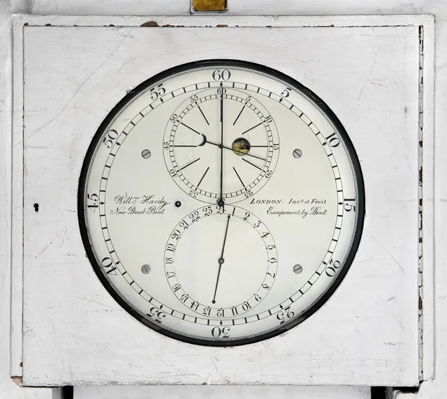
Clocks · c. 1811
An eight-day sidereal regulator, mounted within a stone block at the southern end of the Airy transit circle by William Hardy, London, circa 1811
Royal Museums Greenwich
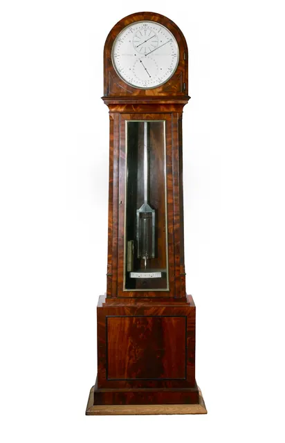
Clocks · c. 1825
An eight-day duration mahogany longcase sidereal regulator, by William Hardy, London, circa 1825
Royal Museums Greenwich
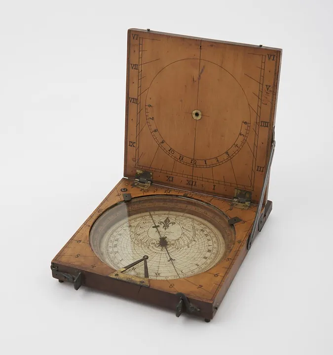
Instruments · 1731–1776
Azimuth compass sundial by James Ferguson, London, England, 1731–1776. Could also be used as a tablet sundial - string gnomon is missing (see note).
Science Museum Group, London
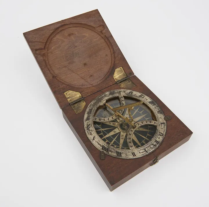
Instruments · 1738–1777
Azimuth sundial 4 3/8" diam, with folding gnomon fitted in mahogany case, made by B. Martin
Science Museum Group, London
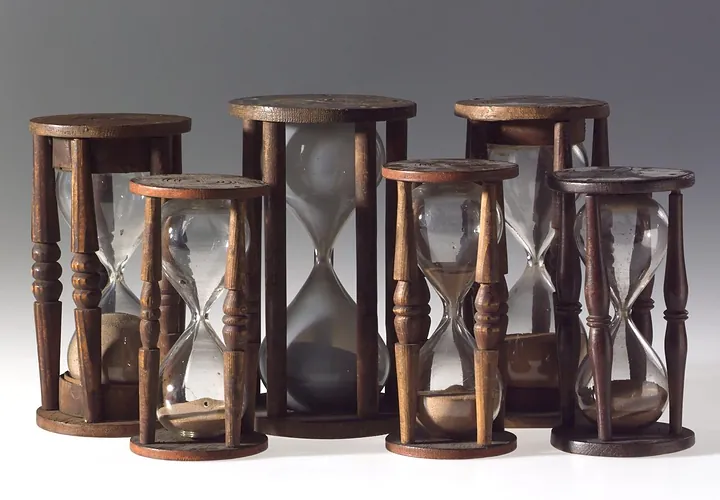
Instruments · 1750–1800
Single sand glass in four pillared wooden mount. 17 minutes. Horne Type B. Second half of the 18th century
Science Museum Group, London
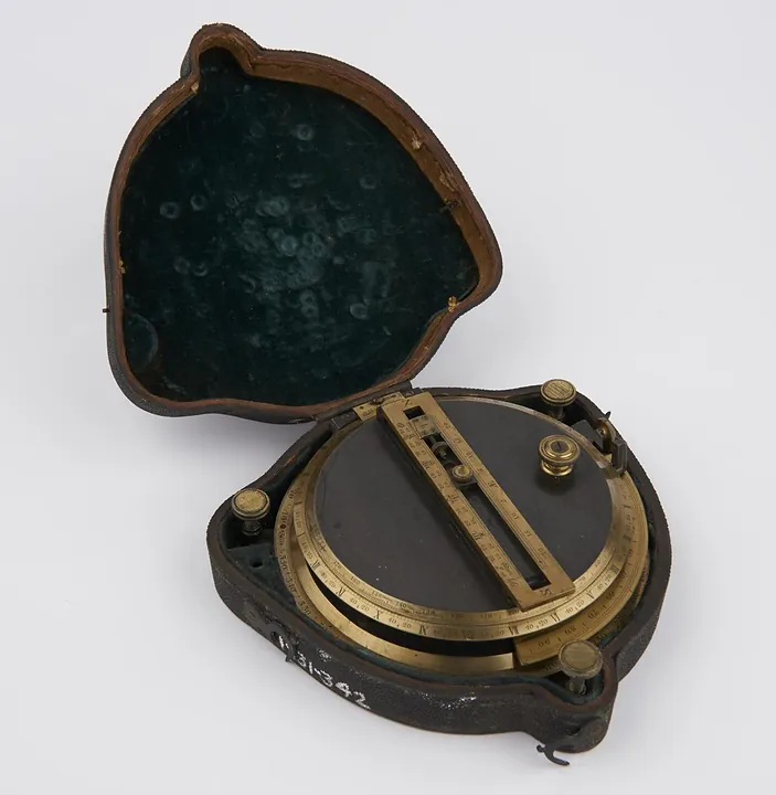
Instruments · 1751–1825
Sundial, by Troughton, in case. Invented and made by Troughton
Science Museum Group, London
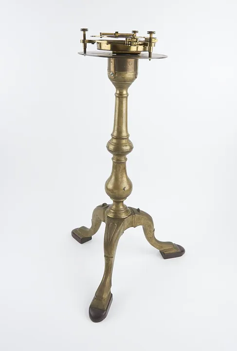
Instruments · 1751–1850
Universal Sundial; by Dollond and large brass stand, engraved "Dollond London" 6-inch hours circle, divided to 2 min, 3 levelling screws
Science Museum Group, London
Instruments · 1760–1769
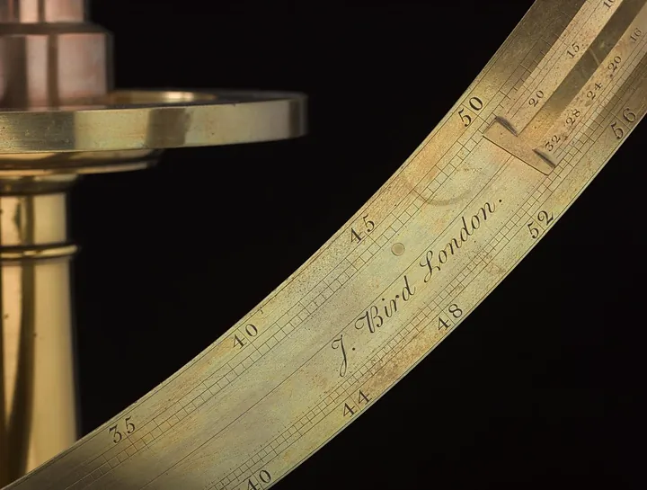
Armillary / astronomical instrument by John Bird, England, 1760–1769
Science Museum Group, London