
Clocks · Astronomical regulator
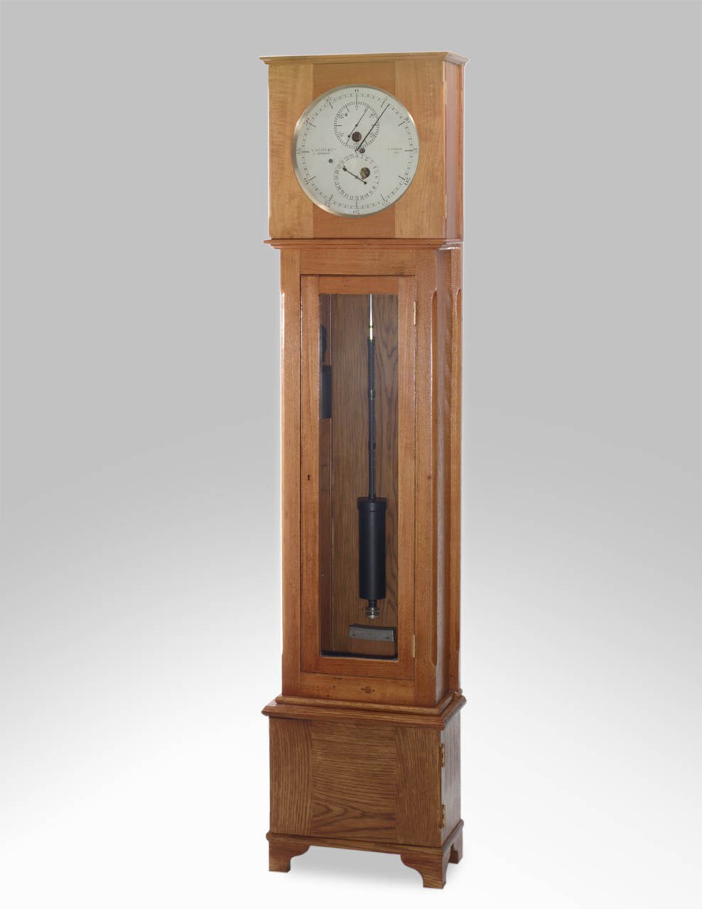
Astronomical regulator no. 2010 by Edward John Dent & Co
- Maker / attribution
- Edward John Dent & Co. (maker)
- Date
- 1870
- Historical period
- Industrial Revolution (1850 – 1900)
- Country of origin
- England
- Object type
- Astronomical regulator
- Materials / technique
- teak; glass; steel; brass; jewel; zinc
- Dimensions
- Overall: 1855 x 430 x 220 mm
- Holding institution
- Royal Museums Greenwich
- Accession / object no.
- ZBA7932
- Credit line
- National Maritime Museum, Greenwich, London
- Catalogue title (original)
- 2010 (English)
View the source record ↗ (opens another website in a new tab)Suggest a correction
Record summary
Held and catalogued by Royal Museums Greenwich (object number ZBA7932), this is an astronomical regulator by Edward John Dent & Co., made in England, dated 1870. The Atlas places it in the Industrial Revolution period (1850 – 1900) of its Clocks collection. Materials and techniques recorded by the source: teak; glass; steel; brass; jewel; zinc. Recorded dimensions: Overall: 1855 x 430 x 220 mm. The record is illustrated with 6 photographs.
Assembled from the source record's structured fields. Dates and attributions are given as the source states them; where a field is missing the Atlas leaves it blank rather than estimating.
Catalogue description
Catalogue description — Royal Museums Greenwich
This clock was one of nine 'secondary' clocks commissioned by Astronomer Royal George Airy for use with altazimuth and equatorial instruments for observing the 1874 Transit of Venus. These wall-sized regulators, each costing £27, originally had wood rod pendulums and according to Dent's estimate with specification, steel pallets. When delivered to the Royal Observatory, the series of clocks were put on test on 'the great stand' on the ground floor of the Great Equatorial building, but 'sympathetic influence' caused the tests to be discontinued. This clock was one of three found to be under-compensated for temperature change and was sent back to Dent for modification. Number '2010' was used at one of the British expedition's temporary observatories on Kerguelen Island in the southern Indian Ocean for observing the 1874 transit of Venus, and again by Captain G. Mackinley to observe the 1882 Transit of Venus; this time at the British station at Up Park Camp, Jamaica. In 1885 it was adapted by E Dent & Co. for use at Devonport dockyard, as part of preliminary trials to establish hourly time signals at primary signal stations at points along the south coast of England. To provide daily time signals to shipping, primarily for rating marine chronometers, it became desirable to provide at primary points throughout the world, daily or hourly means of indicating the exact time. This usually took the form of a ball or similar visual signal mounted at a prominent point within a dockyard or on a headland that was hoisted a few minutes prior to a pre-determined time and dropped exactly at a pre-determined hour of often one o'clock. Traditionally, the operation of these signals relied on a nearby observatory finding time through the observation of the transit of stars, a relatively complicated, costly, and time-consuming process. With the advent of the galvanic telegraph, it became possible to transmit time signals to remote points from one central point almost instantaneously. In this case, the central point was the mean solar standard clock at the Royal Observatory Greenwich. The Greenwich signal could be used to directly activate remote signals or devices such as the timeball at Deal, in Kent, England, but problems with reliability of the telegraph line prevented this direct system from being widely adopted. A more reliable, but slightly less precise system was devised that used the Greenwich signal to correct a remote precision clock (regulator), that in turn would activate the nearby signal. This way, if the Greenwich signal failed, the remote clock would continue running, without correction until the Greenwich signal could be re-established. Converting the clock for its new use involved making the apertures in the dial, and fitting the electrical contacts and electro-magnetic correcting device as described above. In addition, the original wood-rod pendulum was replaced with the present zinc and steel type and an auxiliary pendulum, suspended directly behind the primary zinc and steel pendulum. This auxiliary pendulum (now removed) will almost certainly have been of wood; possibly the original was used. The clock case was extended in depth to accommodate this pendulum and the original wooden panel in the backboard. The backboard was removed and replaced with glass to form a partition between the front and new back compartments. The wooden panel in the trunk door was also replaced with glass. To one side of the rear portion of the case, a solenoid was fitted that operated a latch. Under normal circumstances the latch held the auxiliary pendulum to one side. An external lever just below the trunk door at the centre of the case with an internal arm, enabled the auxiliary pendulum to be manually returned to the latch. Terminals for connecting the various external wires were fitted to the case and a telegraph key placed near the clock to enable the timeball to be dropped at will. A rotary switch near the clock enabled an attendant to operate the magnetic corrector. At a pre-determined time (normally ten o'clock), contacts on the Greenwich Mean Solar Standard (master) clock would automatically close, sending an electrical impulse to the remote clock (in this case at Devonport dockyard). This would activate the solenoid within rear portion of the remote clock case, releasing the auxiliary pendulum. On being released, the auxiliary pendulum was allowed to swing freely in coincidence with the pendulum on the master clock. Although the auxiliary pendulum was not impulsed in any way, it would continue to swing without its arc diminishing appreciably for many minutes. An attendant standing by the remote clock at the time of release would note whether the clock was fast or slow of the Greenwich signal. The difference in phase between the auxiliary and primary (normal) pendulums at the time of release would indicate error. The attendant would then bring the primary pendulum into synchronisation with the auxiliary pendulum by means of the electro-magnetic corrector. When both pendulums swung in exact synchronisation the clock had been brought to time and the current to the electro-magnets would be switched off. Later the same day (normally one hour and 20 seconds after the initial release) the third set of contacts on the remote clock (described above) were automatically closed sending a return signal to Greenwich to confirm the clock had been brought to time. This system continued in use and a record was kept of the error of the daily return signal until 1937. Since then the clock has been partially restored to its original form. The auxiliary pendulum, solenoid, latch and rear portion of the case have been removed and no longer exist. The glass panel in the original backboard has been again replaced with wood and the backboard re-enforced with strips of wood down both sides. The inside of the clock was refurbished and fitted with an oak base by the MoD chronometer workshops at Herstmonceux Castle. The clock wa
Historical context
Industrial Revolution (1850 – 1900)
American interchangeable-parts manufacture; railroad time standards; Swiss and German factory systems.
Factory production transformed the clock into an everyday object. American makers (Seth Thomas, Ansonia, Waterbury) and German factories (Junghans, Gustav Becker, Lenzkirch) sold millions of shelf, wall and alarm clocks worldwide; France produced standardised Paris movements and carriage clocks; electric time distribution began.
Read the period in the timelineMore clocks from this periodEarlier: Precision & Scientific Horology
Atlas type guide
Regulators, wall and Vienna clocks
A regulator is a precision pendulum clock used as a time standard in observatories, workshops and railway offices. Typical features are a deadbeat or Graham escapement, a temperature-compensated pendulum (mercury jar, gridiron or later invar), maintaining power and a regulator dial that separates hours, minutes and seconds. George Graham's deadbeat escapement (c. 1715) and his mercury pendulum, together with Harrison's gridiron, set the pattern for two centuries.
Wall clocks span a much wider range: the elegant Viennese Laterndluhr and Dachluhr of the Biedermeier period, the Dutch stoelklok and staartklok, English 'dial' clocks used in schools, offices and railway stations, and mass-produced spring and weight wall clocks from Germany (Gustav Becker, Junghans, Kienzle) and America.
What to look for
- Deadbeat escapement and compensated pendulum (gridiron rods, mercury jar or wood rod).
- A regulator dial with a large central minute hand and separate hour and seconds dials.
- Vienna regulators: glazed cases, slender pendulum, small weights, enamel two-piece dials.
- German factory trademarks stamped on the backplate (e.g. Gustav Becker anchor and crown, Junghans star).
Dating clues
- Graham-type deadbeat regulators: from c. 1720.
- Viennese Laterndluhr: c. 1800–1850.
- German factory 'Vienna-style' regulators: c. 1870–1930; Gustav Becker serial numbers allow close dating.
General guidance written by the Atlas editors about this kind of object. It is not a statement about this particular piece; for that, rely on the source record above and on physical examination.
Read next:Deadbeat escapementAnchor (recoil) escapementGrasshopper escapement
Related records
Clocks · 1870
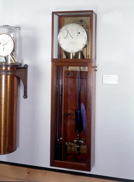
A wall mounted astronomical regulator with Airy’s spring detent escapement, manufactured by E. Dent & Co. No. 1906, c.1870
Royal Museums Greenwich
Instruments · Unknown. Second half 19th century.
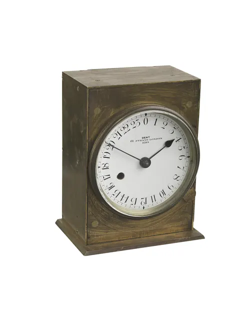
Chronometer no. 1689 by Edward John Dent & Co
Royal Museums Greenwich
Clocks · c. 1842
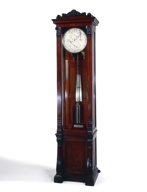
An astronomical longcase regulator by Dent of London, number 587, featuring G.B. Airy’s ‘Remontoir Dead-beat’ escapement, circa 1842
Royal Museums Greenwich
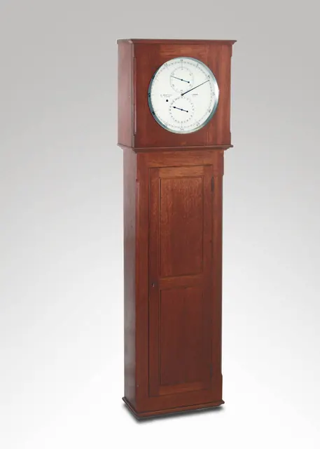
Clocks · c. 1870
Astronomical regulator no. 2011 by Edward John Dent & Co
Royal Museums Greenwich
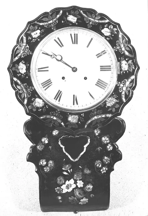
Clocks · 1830–1870
Wall clock in a papier mâché case with painted decoration. English, mid 19th century.
Victoria and Albert Museum, London
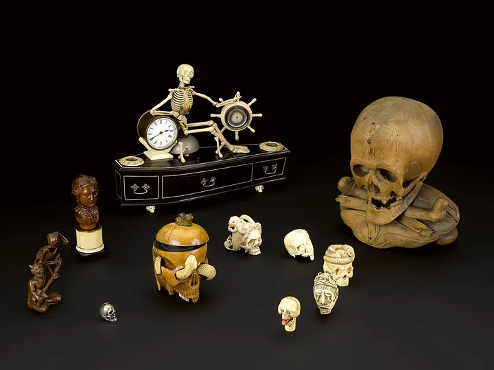
Clocks · 1840–1900
Alarm clock, mounted on model of coffin with skeleton, probably English, 1840–1900
Science Museum Group, London
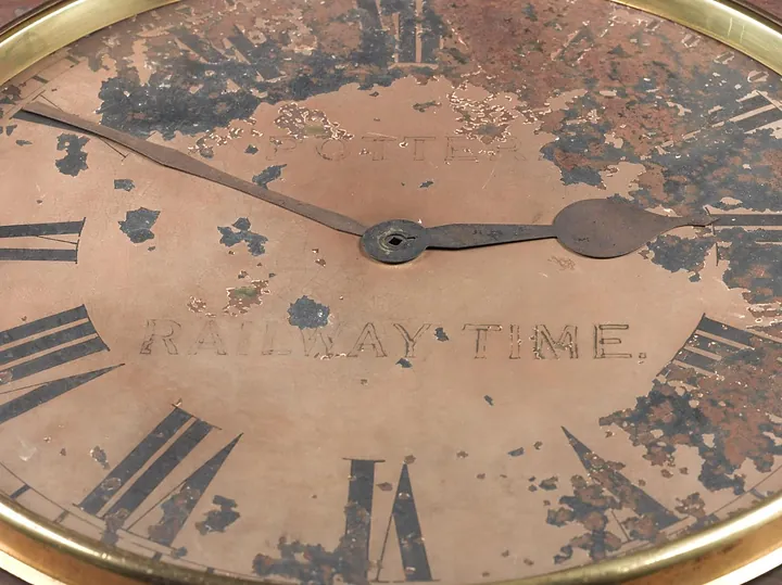
Clocks · 1840–1880
Clock dial marked "Potter, Railway Time" with two hands, unknown maker, British, 1840–1880
Science Museum Group, London
Clocks · 1840–1880
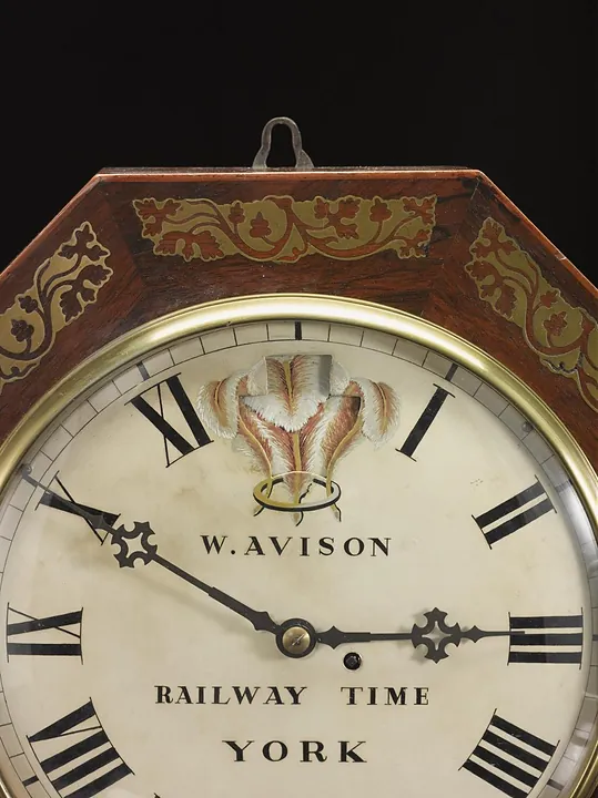
Wall Clock in octagonal case with Prince of Wales Feathers above makers name "W. Avison, Railway Time, York", made by William Avison, England, 1840–1880.
Science Museum Group, London