
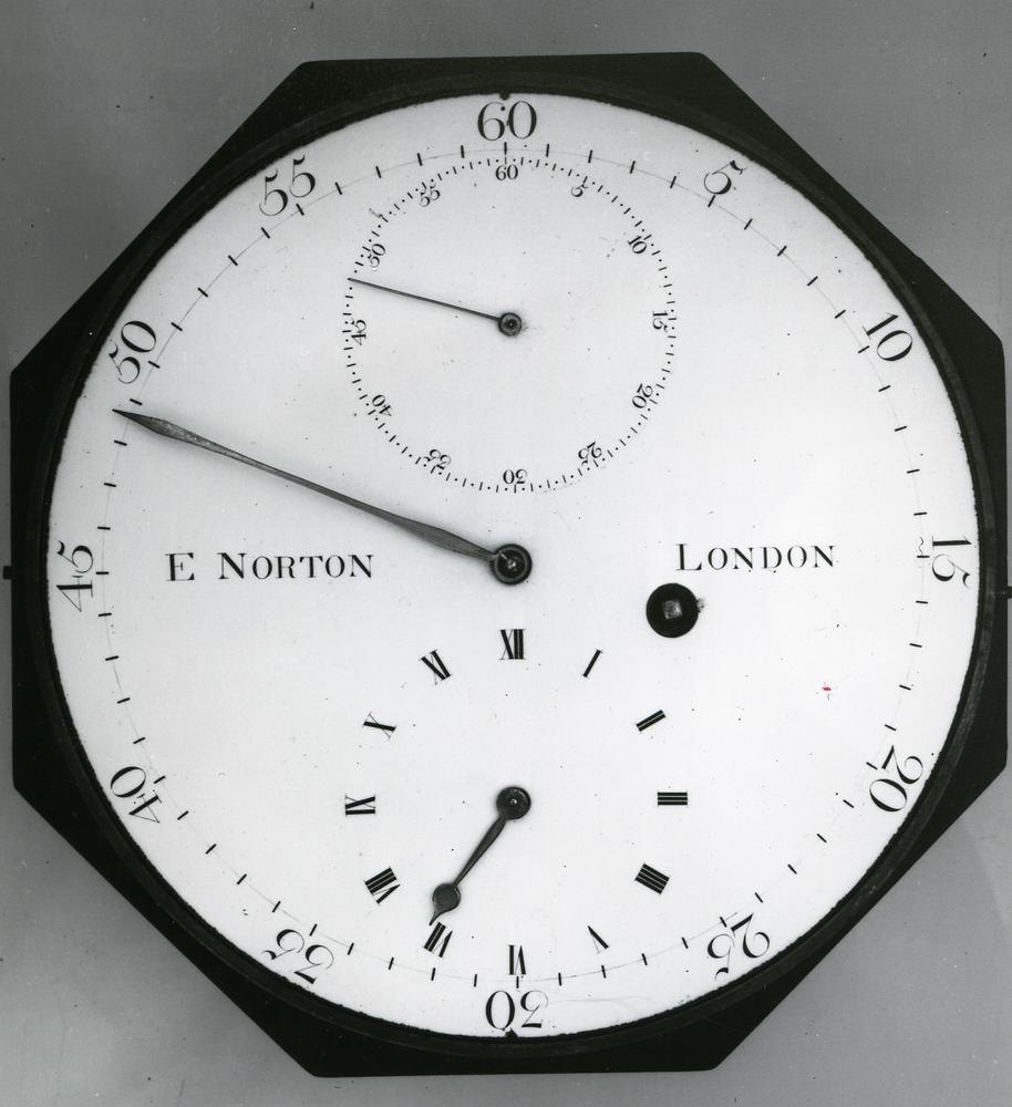
Instruments · Marine chronometer
Marine chronometer by Eardley Norton
- Maker / attribution
- Eardley Norton (Made by)
- Date
- 1785–1795
- Historical period
- Precision & Scientific Horology (1750 – 1850)
- Country of origin
- England
- Place
- London (England) (St John Street)
- Object type
- Marine chronometer
- Materials / technique
- mahogany
- Holding institution
- British Museum
- Accession / object no.
- 1958,1006.1940
- Credit line
- British Museum, London
- Catalogue title (original)
- Marine chronometer; hexagonal; twenty-four hour movement; two-arm balance; Earnshaw detent escapement; circular white enamel dial; mahogany case (English)
View the source record ↗ (opens another website in a new tab)Suggest a correction
Record summary
Held and catalogued by British Museum (object number 1958,1006.1940), this is a marine chronometer by Eardley Norton, made in London (England) (St John Street), dated 1785–1795. The Atlas places it in the Precision & Scientific Horology period (1750 – 1850) of its Instruments collection. Materials and techniques recorded by the source: mahogany. The record is illustrated with 6 photographs.
Assembled from the source record's structured fields. Dates and attributions are given as the source states them; where a field is missing the Atlas leaves it blank rather than estimating.
Catalogue description
Description — British Museum
Marine chronometer; hexagonal; twenty-four hour movement; two-arm balance; Earnshaw detent escapement; circular white enamel dial; mahogany case.
Curator's comments — British Museum
Comment from Anthony G. Randall and Richard Good, Catalogue of Watches in the British Museum. Vol. VI (1990) Made by Eardley Norton, c. 1790 Marine Chronometer Signature: On the dial 'E NORTON LONDON'. On the back plate '2322'. Box: The movement contained in a brass drum rigidly fixed inside an octagonal mahogany base. A brass bezel overlapping the base fits on the outside of the drum and is secured bayonet fashion, it has a bevel-edged flat glass. It is now impossible to remove the brass drum from the base, but tapped holes coming through the side of the latter may have been for the pivoting points of a gimbal ring. There are also two brass securing screws in the base. The dial plate fits flush in a recess in the top of the drum, with a positioning peg. Box 148 mm across the flats, h. 78 mm overall. Dial and hands: Slightly domed enamel regulator dial attached to the dial plate by the two small screws on the edge. There is no sign of scribed divisions under the enamel of the minute and seconds markings. Gold hands, hour hand not original. Movement: Dial plate diam. 139 mm; front plate diam. 108.4 mm; back plate diam. 108.4 mm; frame h. 30.1 mm. Frame: Full plate construction with four baluster pillars, the back plate retained by pins. The dial plate, with pierced centre to clear the motion and under dial work, attached to the front plate by four pillars and pins. It is of much larger diameter than the front plate and appears once to have been fitted with a case catch and hinge, various holes remaining. The balance staff passes through the frame and is pivoted on the front plate and in a pierced bridge on the back plate. There are a number of unused holes, including a corresponding pair in the plates near their edge, beside the fourth wheel, with a cock on the front plate, possibly for a train or balance stop device, and one in a pillar which is threaded. Fusee: Reversed fusee fitted with the usual stop-work and maintaining power. The barrel is of unusually large diameter and made from a piece of strip bent and soldered and the bottom soldered on. The setting-up-work is planted on the back plate with a very short extended arbor square on that end for setting up. The mainspring is grained white and not blued, it is not signed but punched with the figure 3 at the end, and hooked with hook and eye to both the solid unsnailed arbor and the barrel wall. The fusee has a single winding click and a brass maintaining wheel, the detent and the stop arm are fitted with brass return springs. Going train: The wheels riveted to the steel pinions; these, their arbors and the pivots polished. Jewelling: Only the pivots of the escape pinion arbor and balance staff in pierced jewels with flat endstones crudely set in strips of brass. The pierced jewels curved towards the endstones and with a sink on both sides. Escapement: Spring detent escapement of Earnshaw type but of massive proportions. The brass escape wheel sunk out on one side with only the tips of the teeth left the full thickness. The grained steel impulse roller set with a jewel leaning towards a radial to the tip. The discharge roller of brass, with an adjusting flat and a jewel set in a hole breaking into the edge. The detent straight except for the foot set sideways and screwed to a brass arm on the underside of the back plate. There was once an adjusting screw set in a slot in the edge of the back plate acting on the brass arm to move the detent towards or away from the balance axis. This screw has broken off and the arm is now fixed with two screws. The passing spring is steel, held under a screw head and the detent slotted for a flat locking stone. Banking for the detent is provided against a screw head set in a brass bracket screwed to the underside of the back plate. Balance: Bimetallic two-armed balance similar to the Arnold 'z' type with the rim sections screwed to integral blocks on the ends of the cross bar. There are steel timing screws at the ends of the arms and similar compensation screws set tangentially in brass blocks screwed to the free ends of the rims. The balance is riveted to a brass collet on the staff. Diam. of rim 39.9 mm, h. 4.3 mm. Balance spring: Blued steel spiral spring of about 5½ turns, without an overcoil or terminal curve, free-sprung to a brass stud on the back plate under the balance. Pinning to the stud is by a square pin in the square hole and to the collet by a wedge-shaped pin in a slot in the edge of the ring-shaped brass collet. Going-train counts: Great wheel (fusee) 48 teeth Centre pinion 12 leaves, wheel 64 teeth, 4 arms Third pinion 8 leaves, wheel 60 teeth, 4 arms Fourth pinion 8 leaves, wheel 56 teeth, 4 arms Escape pinion 7 leaves, wheel 15 teeth, 4 arms Beats per hour: 14,400 Motion work: Cannon pinion 14 leaves (held by a pin through the arbor), minute pinion 14 leaves Hour wheel 56 teeth (held by a pin through an arbor pivoted in the frame), minute wheel 42 teeth Provenance: Ilbert collection; Ilbert states that he acquired this chronometer from Clowes in 1937. Presented by Mr Gilbert Edgar C.B.E. in 1958. Exhibited: British Clockmakers Heritage Exhibition, Science Museum, London, May-September 1952; British Watches and Clocks, City of Birmingham Museum of Science and Industry, October 1953-February 1954. Bibliography: Bertele 1981, p. 150.
Inscriptions & marks
signature; Eardley Norton, London, No.2322
Provenance
Previous owner/ex-collection:, Courtenay Adrian Ilbert; Donated by:, Gilbert Edgar; Acquired 1958
Historical context
Precision & Scientific Horology (1750 – 1850)
Harrison solves longitude; Mudge invents the lever; Breguet's Paris workshop defines the modern watch.
The longitude problem was solved by the marine chronometer and lunar distance methods; dividing engines made precision scales possible, and observatories set time by transit instruments.
Read the period in the timelineMore instruments from this periodEarlier: Early Modern Horology
Atlas type guide
Marine chronometers
A marine chronometer is a precision timekeeper carried at sea to find longitude: the navigator compares local noon, observed with a sextant, with the time at a reference meridian kept by the chronometer. Each hour of difference corresponds to fifteen degrees of longitude. John Harrison proved the method in the 1760s; Pierre Le Roy, Ferdinand Berthoud, John Arnold and Thomas Earnshaw then developed the detent escapement and the compensation balance that made chronometers practical to manufacture.
By the nineteenth century London, Liverpool, Le Locle and Glashütte supplied navies and merchant fleets. A typical box chronometer has a spring-detent escapement, a fusee to equalise mainspring torque, a bimetallic compensation balance with a helical balance spring, and is mounted in gimbals inside a wooden box so that it stays level.
What to look for
- Gimbals and a three-tier wooden box with a glazed inner lid.
- A power-reserve ('up and down') indicator on the dial, usually showing 56 hours on two-day instruments.
- Spring-detent escapement and a cylindrical (helical) balance spring visible through the movement.
- Admiralty or navy marks (broad arrow), and rating certificates from observatories.
- The maker's number on the dial and movement; many makers' registers survive, allowing dating.
Dating clues
- Earnshaw-type spring-detent chronometers became standard after about 1800.
- Auxiliary compensation devices on the balance appear from the mid-nineteenth century.
- Quartz and radio time signals ended routine use of mechanical chronometers in the 1970s and 1980s.
General guidance written by the Atlas editors about this kind of object. It is not a statement about this particular piece; for that, rely on the source record above and on physical examination.
Read next:Detent escapement
Related records
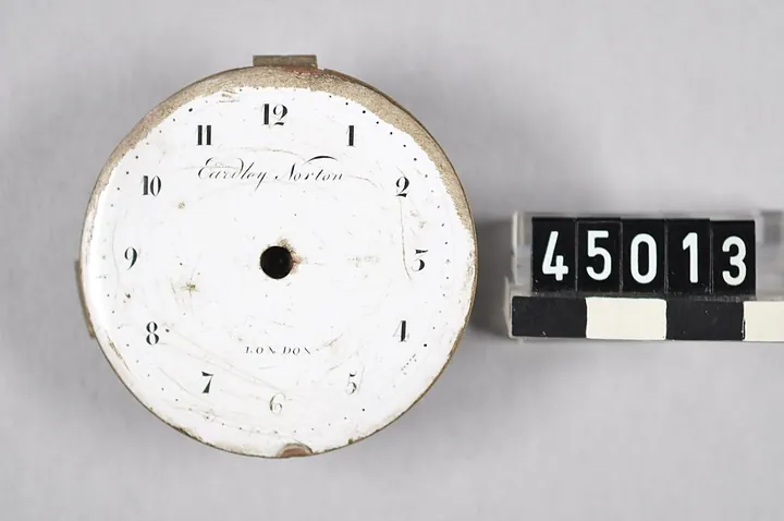
Movements & Components · 1700–1799
Watch movement by Eardley Norton, England, 1700–1799 (no. TEKS0048447)
Swedish National Museum of Science and Technology
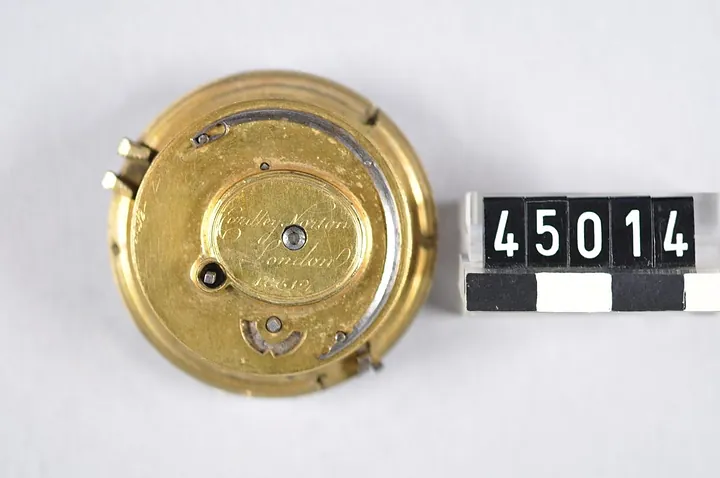
Movements & Components · 1700–1799
Watch movement by Eardley Norton, England, 1700–1799 (no. TEKS0048448)
Swedish National Museum of Science and Technology
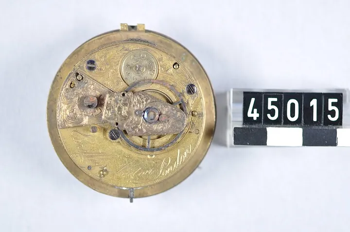
Movements & Components · 1700–1799
Watch movement by Eardley Norton, England, 1700–1799 (no. TEKS0048449)
Swedish National Museum of Science and Technology
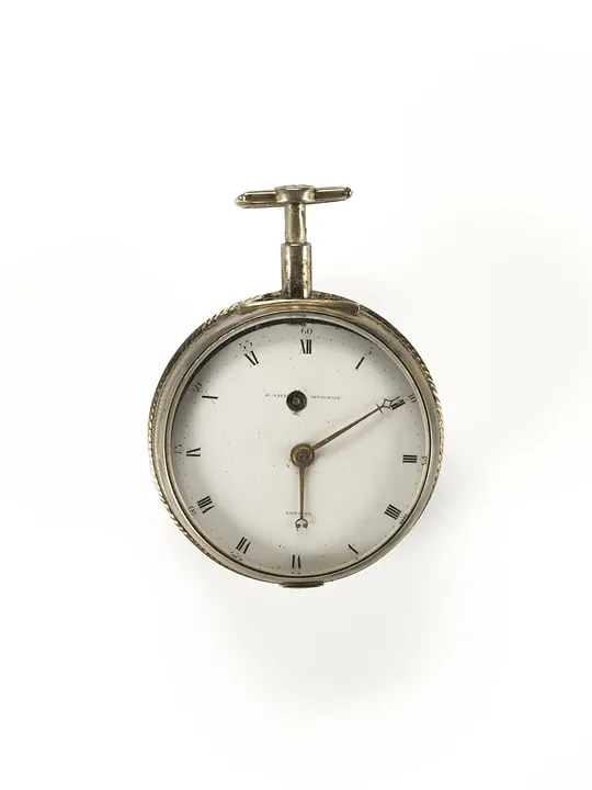
Pocket Watches · 1770–1794
Repeater in silver case by Eardley Norton, London, no.2143 going barrel, cylinder (inner case only ?), 1770–1794, donated byt Evan Roberts in 1916
Science Museum Group, London
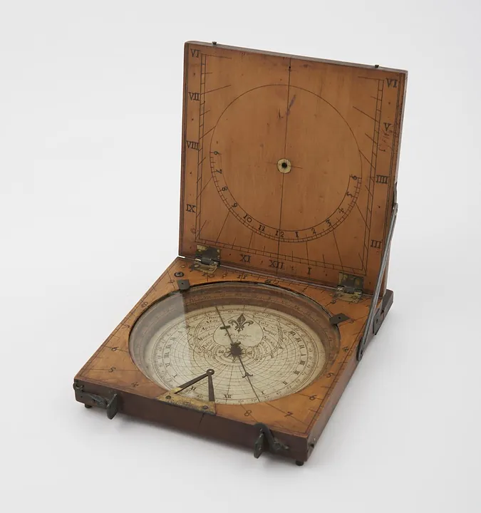
Instruments · 1731–1776
Azimuth compass sundial by James Ferguson, London, England, 1731–1776. Could also be used as a tablet sundial - string gnomon is missing (see note).
Science Museum Group, London
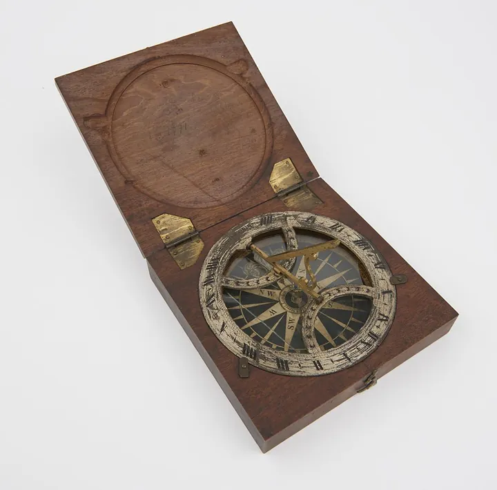
Instruments · 1738–1777
Azimuth sundial 4 3/8" diam, with folding gnomon fitted in mahogany case, made by B. Martin
Science Museum Group, London
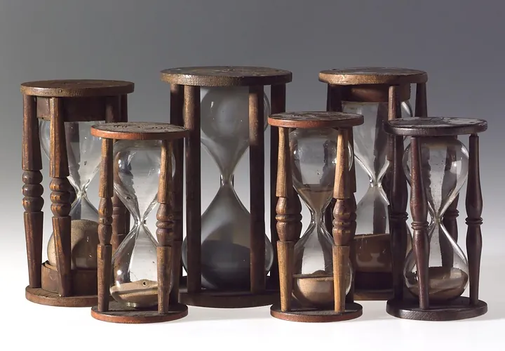
Instruments · 1750–1800
Single sand glass in four pillared wooden mount. 17 minutes. Horne Type B. Second half of the 18th century
Science Museum Group, London
Instruments · 1751–1825
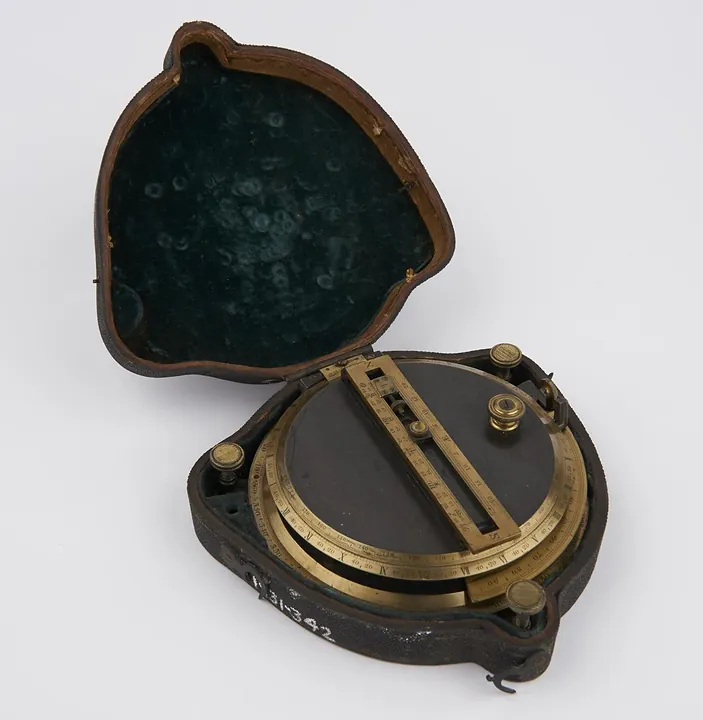
Sundial, by Troughton, in case. Invented and made by Troughton
Science Museum Group, London