
Instruments · Marine chronometer
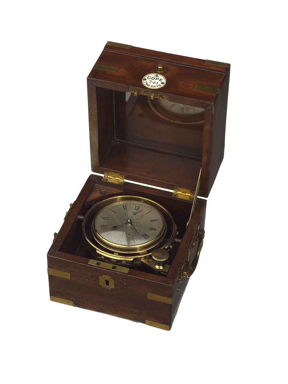
Marine chronometer no. 741 by Charles John Cope
- Maker / attribution
- Charles John Cope (maker)
- Date
- c. 1820
- Historical period
- Precision & Scientific Horology (1750 – 1850)
- Country of origin
- Unrecorded in source
- Object type
- Marine chronometer
- Dimensions
- Overall: 160 x 170 x 165 mm
- Holding institution
- Royal Museums Greenwich
- Accession / object no.
- ZAA0053
- Credit line
- National Maritime Museum, Greenwich, London
- Catalogue title (original)
- 741 (English)
View the source record ↗ (opens another website in a new tab)Suggest a correction
Record summary
Held and catalogued by Royal Museums Greenwich (object number ZAA0053), this is a marine chronometer by Charles John Cope, dated c. 1820. The Atlas places it in the Precision & Scientific Horology period (1750 – 1850) of its Instruments collection. Recorded dimensions: Overall: 160 x 170 x 165 mm. The record is illustrated with 2 photographs.
Assembled from the source record's structured fields. Dates and attributions are given as the source states them; where a field is missing the Atlas leaves it blank rather than estimating.
Catalogue description
Catalogue description — Royal Museums Greenwich
Cope, London c.1829 No.741 2 day marine chronometer in brass bound mahogany box Cope,…………… Box/Mounting Three-tier brass-bound mahogany box measuring 160mm high, 173mm wide, and 164mm deep. The lid has a hollow-corner lozenge lacquered-brass plate inlaid in the top, with brass butt- hinges, opening to 90° to reveal a glazed panel retained with narrow wooden beading. The front of the upper half has a brass push-button lid catch with inlaid brass ‘petal’ escutcheon, and a small circular ivory tablet, engraved : “↑ / COPE / 741 / TWO DAYS”, below. The lock on the lower half has an inlaid brass ‘hollow-corner’ lozenge escutcheon. The box is of fine, concealed dovetailed construction at all four corners, and the upper half has plain hinges, originally opening right over, but now limited to 90° owing to a later brass strut inside on the right hand side. There would almost certainly have been a baize covering running round the upper edge of the lower half, and forming a dust seal when closed, but this is now missing. The inside of the lower box has been strengthened with two pieces of mahogany quadrant running down the left and right hand side (3 brass`screws each side), and the top of the lid has been secured with 8 brass screws on top. The box fittings are of the standard layout. There are brass drop handles on the sides, the gimbal screws threaded into bevelled brass blocks on the outsides of the box. The narrow, quite close-fitting lacquered brass gimbal ring has an adjustable curved plate for supporting the front gimbal pivot and adjustable curved plates on the bowl for the fixing the front and back pivot blocks themselves. The cast brass bowl has a slightly off-centre swiveling shutter on ther base, the underside of the shutter scratched: “741”. The upper part of the bowl sweeps out to a somewhat larger diameter, threaded for the bezel. Narrow brass screwed bezel (2 turns) with a short, flat side and narrow mouldings, with thin convex glass over the dial, and scratched:”71” on the underside. The winding key is no\longer present,. The underside of the box has a green baize covering. Dial and hands The 82.8 mm Ø, engraved and wax-filled, silvered-brass dial small counter-sunk screws at III and IX o’clock, which fix it into a recess in the brass edge. The pillar plate of the movement seats in a deep recess on the other side of the brass edge, with a pin in the brass edge to locate it and two blued steel dog-screws retaining it. The brass edge then seats in the recess in the bowl, a pin at XII and a notch in the bowl orientating it correctly. The dial has roman hour numerals and the seconds dial, below the centre, has arabic ten-second figures with straight batons at alternate five-second intervals. An up and down dial below XII is marked in 8 hour intervals and has “UP” next to “0”, “WIND” next to “24” and “Down” next to “48”. The main dial is signed across the centre: “CHAs. JNo. COPE / Rathbone Place LONDON / NO. 741”. In side the seconds dial is engraved “↑”.The brass edge is scratched “741” and “Set up 10 teeth”. Blued steel spade and poker-hands with a fine, blued steel pointer seconds hand with a counter-poised tail, and blued steel pointer up and down hand. Movement Full-plate fusee movement with four pillars with flanges and fins at either end and one fin in the lower middle, screwed to the potence plate with blued steel screws. The potence plate is engraved: “↑ / CHAs. JNo. COPE , Rathbone Place LONDON 741”. The table of the balance cock is also engraved: “↑”. The underside of the blued steel set up ratchet wheel is scratch-marked for position against a nick on the edge of the square, and it also has two triangular dots (polishing points?). The double-nose set-up click is in blued steel. There is a small drilled dot on the barrel bar by the ratchet wheel to mark set-up positions against a dot on the top surface of the wheel, and a one dot and a two dot set-up / isochronising marks on the underside of the pillar plate, corresponding with a dot on the end of the barrel arbor pivot. There is a polishing point on the inside of the maintaining power detent, and the inside of the potence plate, the train bar, the fusee bar and the undersides of the pillar plate, the barrel bar, the barrel, the balance cock foot, the potence, the maintaining power wheel and the great wheel, are marked with one dot. The great wheel is scratched “29/10/59” under the blued steel cap, and: “H A July 1856”, “H A October 1859”, “w e c”, and “H J A / Cleaned 8 March 1864”. The brass ratchet wheel is scratched: “741”. The straight sided fusee pipe is dot-marked for position and the fusee cap is dot marked for the pin entry hole. The later, signed blued steel mainspring has a steel square hooking in the barrel. There is a five-wheel train including great wheel, the fusee with Harrison’s maintaining power and with a straight-sided fusee pipe push-fitted to the square. The train wheels are brass with the third, fourth and escape wheels run on a bar on the pillar plate with the lower fusee pivot run on a separate bar. All train holes have been plugged and re-pitched from new, including the maintaining power detent. Escapement, balance, spring and jewelling Earnshaw-type spring detent escapement, the fine grey-finished foot detent with gold passing spring screwed to the side, and pink locking stone in a pipe. The detent banks against a gilt-brass banking piece, fixed alongside the detent and there is a small viewing/locking hole directly above, for viewing the dcepth of engagement of the locking stone, and possibly for blocking the train with a pin into the escape teeth. Bright, grey-finished impulse roller with polished edge and polished impulse face, and discharge roller with a light pink stone inset. The standard, oversprung bimetal balance, has round brass compensation weights mounted on the rim segments at 90° to the arms. Brass mean time nuts are mounted on threads at the ends of the arms, and there are spare thr
Historical context
Precision & Scientific Horology (1750 – 1850)
Harrison solves longitude; Mudge invents the lever; Breguet's Paris workshop defines the modern watch.
The longitude problem was solved by the marine chronometer and lunar distance methods; dividing engines made precision scales possible, and observatories set time by transit instruments.
Read the period in the timelineMore instruments from this periodEarlier: Early Modern Horology
Atlas type guide
Marine chronometers
A marine chronometer is a precision timekeeper carried at sea to find longitude: the navigator compares local noon, observed with a sextant, with the time at a reference meridian kept by the chronometer. Each hour of difference corresponds to fifteen degrees of longitude. John Harrison proved the method in the 1760s; Pierre Le Roy, Ferdinand Berthoud, John Arnold and Thomas Earnshaw then developed the detent escapement and the compensation balance that made chronometers practical to manufacture.
By the nineteenth century London, Liverpool, Le Locle and Glashütte supplied navies and merchant fleets. A typical box chronometer has a spring-detent escapement, a fusee to equalise mainspring torque, a bimetallic compensation balance with a helical balance spring, and is mounted in gimbals inside a wooden box so that it stays level.
What to look for
- Gimbals and a three-tier wooden box with a glazed inner lid.
- A power-reserve ('up and down') indicator on the dial, usually showing 56 hours on two-day instruments.
- Spring-detent escapement and a cylindrical (helical) balance spring visible through the movement.
- Admiralty or navy marks (broad arrow), and rating certificates from observatories.
- The maker's number on the dial and movement; many makers' registers survive, allowing dating.
Dating clues
- Earnshaw-type spring-detent chronometers became standard after about 1800.
- Auxiliary compensation devices on the balance appear from the mid-nineteenth century.
- Quartz and radio time signals ended routine use of mechanical chronometers in the 1970s and 1980s.
General guidance written by the Atlas editors about this kind of object. It is not a statement about this particular piece; for that, rely on the source record above and on physical examination.
Related records
Instruments · 1726–1775
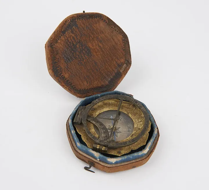
Universal equinoctial sundial of the Augsburg type, signed on the base "L T M" (Ludwig Theodatus Muller). In original case. German, mid 18th century. (B1670)
Science Museum Group, London
Instruments · 1731–1776
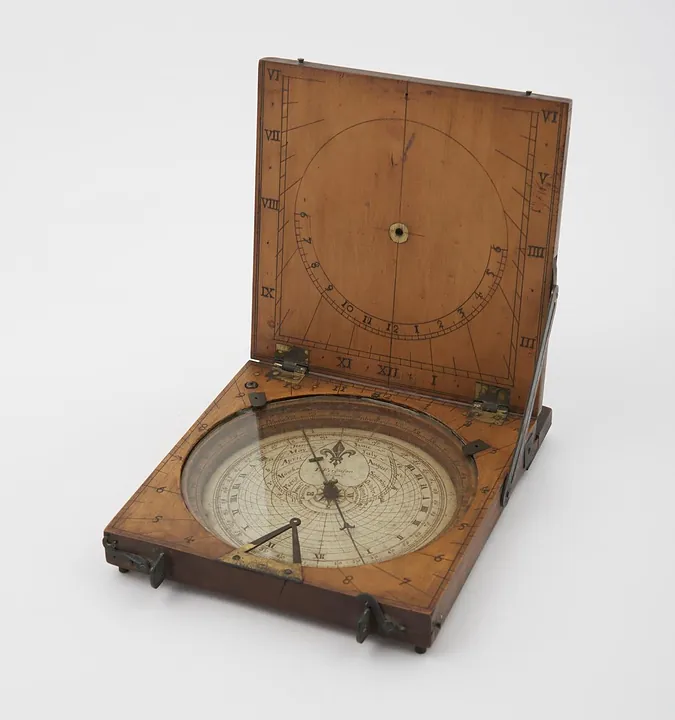
Azimuth compass sundial by James Ferguson, London, England, 1731–1776. Could also be used as a tablet sundial - string gnomon is missing (see note).
Science Museum Group, London
Instruments · 1734–1770
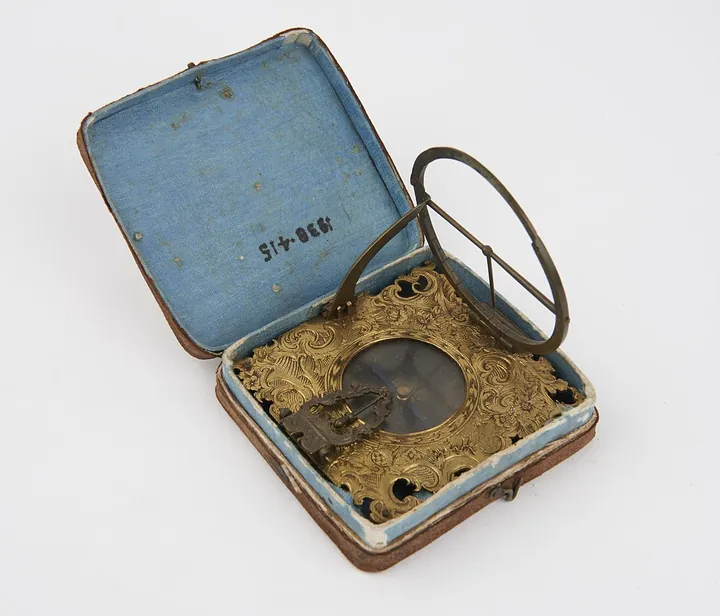
Sundial by Ludwig Theodatus Muller, Germany, 1734–1770 (no. 1938-415)
Science Museum Group, London
Instruments · 1734–1770
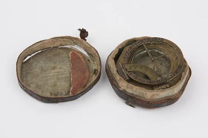
Sundial by Ludwig Theodatus Muller, Germany, 1734–1770 (no. 1991-138)
Science Museum Group, London
Instruments · 1734–1770
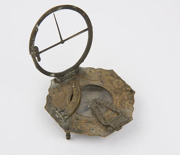
Sundial by Ludwig Theodatus Muller, Germany, 1734–1770 (no. 1991-192)
Science Museum Group, London
Instruments · 1738–1777
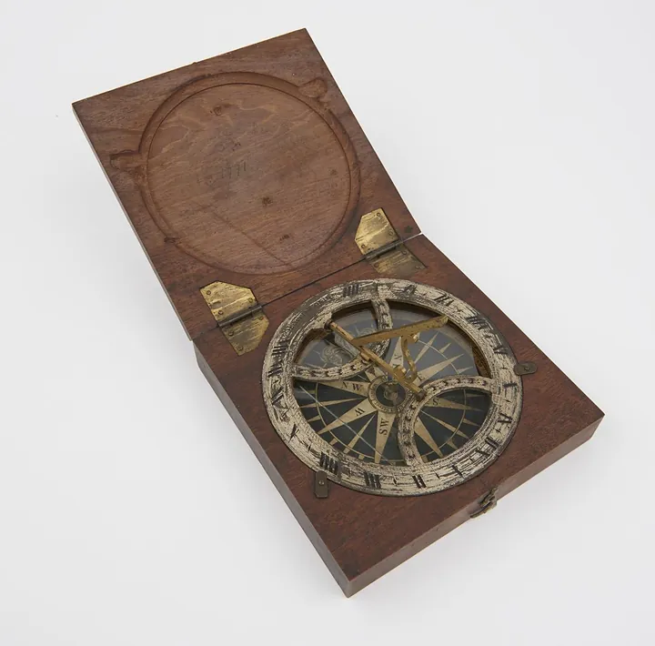
Azimuth sundial 4 3/8" diam, with folding gnomon fitted in mahogany case, made by B. Martin
Science Museum Group, London
Instruments · 1745–1755
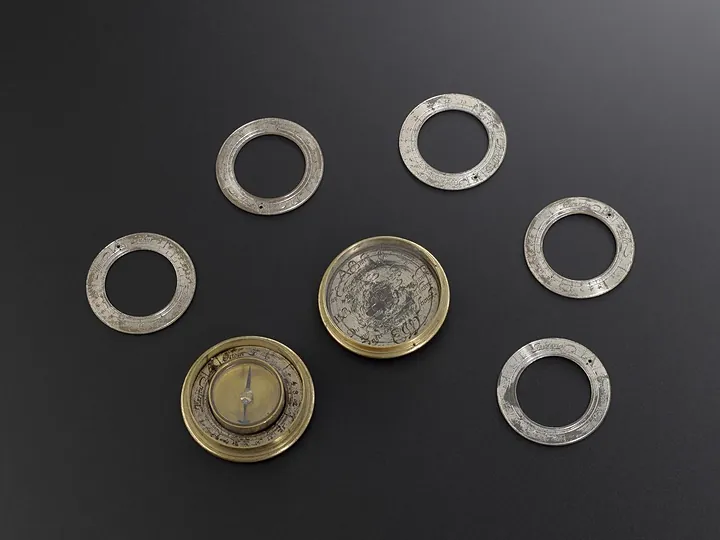
Magnetic Sundial with six loose hour rings
Science Museum Group, London
Instruments · 1745–1755
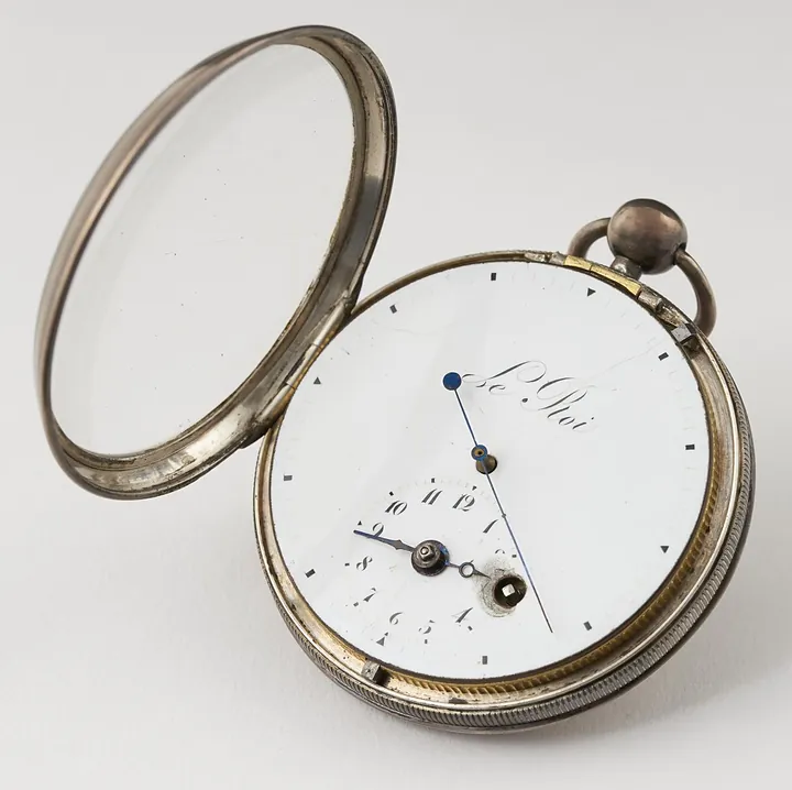
Verge stop-watch with centre seconds hand, by Le Roi, 1745–1755 (see note).
Science Museum Group, London