
Instruments · Marine chronometer
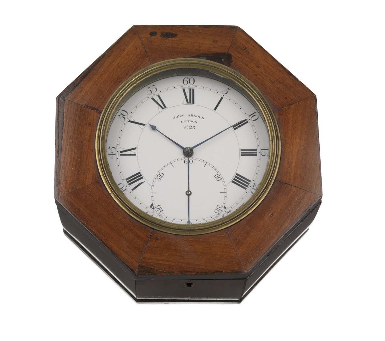
Marine chronometer no. 23 by John Roger Arnold
- Maker / attribution
- John Roger Arnold (maker); John Arnold & Son (maker)
- Date
- c. 1784
- Historical period
- Precision & Scientific Horology (1750 – 1850)
- Country of origin
- England
- Object type
- Marine chronometer
- Materials / technique
- mahogany
- Dimensions
- Overall: 165 x 165 x 90 mm
- Holding institution
- Royal Museums Greenwich
- Accession / object no.
- ZAA0012
- Credit line
- National Maritime Museum, Greenwich, London, Caird Collection
- Catalogue title (original)
- 23 (English)
View the source record ↗ (opens another website in a new tab)Suggest a correction
Record summary
Held and catalogued by Royal Museums Greenwich (object number ZAA0012), this is a marine chronometer by John Roger Arnold, made in England, dated c. 1784. The Atlas places it in the Precision & Scientific Horology period (1750 – 1850) of its Instruments collection. Materials and techniques recorded by the source: mahogany. Recorded dimensions: Overall: 165 x 165 x 90 mm. The record is illustrated with 6 photographs.
Assembled from the source record's structured fields. Dates and attributions are given as the source states them; where a field is missing the Atlas leaves it blank rather than estimating.
Catalogue description
Catalogue description — Royal Museums Greenwich
John Arnold & Son, London c.1784 No.23 Two-day marine chronometer in mahogany box ZAA0012 Box/Mounting Octagonal mahogany box, measuring 93mm high, 167mm wide, and 167mm deep. The box is veneered in mahogany on a mahogany carcass with concealed joints. The box has a slightly stepped base, standing proud round all eight sides by about 1mm. Inside the base of the box is penciled: 25 [sic]. The lid of the box, which is constructed of eight segments with radial joints, has an 11 cm glazed aperture for viewing the dial, with a narrow moulded brass bezel, retaining the flat glass on top, the glass secured underneath with a fillet of plaster. Inside the box, an octagonal mahogany frame seats in a rebate inside the top edge. The brass edge of the movement, which is formed of a wide flange, integral with the pillar plate, is screwed to this frame from below with three steel screws. The frame and movement are not secured in any other way inside the box and, with the lid opened and the box turned over, the movement on the frame can simply be lowered out. The lid is on two later (probably twentieth century) brass hinges, and opens right over to 180°. There is a small steel lock on the front of the box with a simple narrow brass escutcheon flush-mounted on the keyhole. The underside of the plain mahogany base of the box has inset a circular swiveling brass dust shutter, a hole in which will line up with a brass tube mounted from inside the box, and forming a pipe for the winding square of the movement. There are pairs of holes on the left and right hand sides of the octagonal box, which were probably where a loop handle was fitted. Dial and Hands The 106.1 mm Ø white enamel dial is attached to the pillar plate of the movement with three pinned feet, the dial fitting closely in a recess in the plate, the flange outside that diameter forming the brass edge. The dial has roman hour numerals and arabic five-minute figures outside the minutes circle, and there is a large seconds indication below the centre. The seconds dial has arabic ten-seconds figures, with straight radial batons at five second intervals. The dial is signed across the upper centre: JOHN ARNOLD / LONDON / No.23. On the back of the dial, enameled over the counter-enamel, in red, is: N 23. There is also the remains of black paper tape which appears to have spanned across the centre hole at some stage. Blued-steel spade and poker hands with a fine, blued-steel pointer seconds hand with polished slotted-screw centre and a counter-poised tail. Movement Full-plate fusee movement with four slightly tapered cannon style pillars, each with one fin at either end, the potence plate fixed with four blued-steel screws, the heads counter-bored flush with the plate. The potence plate is engraved: John Arnold & Son / London, and No.23 Inv. et Fecit. The pillar plate also forms the brass edge. The general level of finish of the movement is high with all movement parts flat-polished and lightly curled. The underside of the pillar plate is scratched: 23 and X at the 60 minutes position. The barrel, the set-up wheel, the great wheel, the maintaining wheel and the fusee are marked: V and the underside of the balance cock foot is scratched: VI. The fourth wheel is marked with a single drilled dot. The balance cock and the potence each have two steel steady pins. The stop iron for the fusee is attached to the potence plate from above with a counter-bored blued-steel screw. The rather coarse, somewhat blistered, powerful, blued-steel mainspring has a fixed round hooking in the barrel and is unsigned. The dot-marked steel set up ratchet wheel and click, with steel return spring, are mounted under the barrel. The fusee has Harrison’s maintaining power, the steel detent mounted on a brass collet on the steel arbor. The fusee is mounted with a large dust cup, a push-fit on the square. Both the ratchet wheel and the grained steel fusee cap are dot-marked and attached with two polished steel screws. There is a four-wheel train and a great wheel, the third and fourth run on a bar on the pillar plate. The quality of the brass used in the wheel work is not perfect, some blistering evident on the surfaces of the centre and third wheels. Escapement, Balance, Spring and Jewelling Early Arnold spring detent escapement with brass escape wheel and grained steel foot detent screwed directly on the potence plate, the body of the detent suspended in a slot in the plate and with brass banking screw angled alongside in the plate. The detent has a riveted-on, gold passing spring running alongside the detent blade, and with a clear jewelled locking stone. A brass plugged hole in the detent blade adjacent to the rivet for the current passing spring suggests this passing spring is a replacement. The impulse roller has a radially disposed, clear impulse jewel and the discharge roller has a similar stone inset. The engagement of the wheel teeth with the impulse pallet is as Arnold’s usual arrangement, with the tooth only half engaged with the pallet and always acting on the pallet edge. As currently set up the wheel drops on before the line of centres, as Arnold intended, and the curved faces of the teeth are worn in consequence, in the usual way. The early Arnold “Z” balance has straight, bevelled steel arms and the pivots on the staff are parallel with a straight sided cone behind. The two bimetal rim segments, which are screwed to the ends of the arms, are of blued-steel and brass on the outside, soldered in place but with one rivet in the middle of each bimetal where it was held in place during soldering. The rims have mean-time screws at the base of the segments and with brass ‘bevelled cylinder’ compensation weights screwed on the curved threaded ends of the segments. The blued-steel helical balance spring has terminals on both ends, the upper terminal clamped under a polished steel piece attached to an adjustable brass pointer stud. The stud is mounted on the top of the balance
Historical context
Precision & Scientific Horology (1750 – 1850)
Harrison solves longitude; Mudge invents the lever; Breguet's Paris workshop defines the modern watch.
The longitude problem was solved by the marine chronometer and lunar distance methods; dividing engines made precision scales possible, and observatories set time by transit instruments.
Read the period in the timelineMore instruments from this periodEarlier: Early Modern Horology
Atlas type guide
Marine chronometers
A marine chronometer is a precision timekeeper carried at sea to find longitude: the navigator compares local noon, observed with a sextant, with the time at a reference meridian kept by the chronometer. Each hour of difference corresponds to fifteen degrees of longitude. John Harrison proved the method in the 1760s; Pierre Le Roy, Ferdinand Berthoud, John Arnold and Thomas Earnshaw then developed the detent escapement and the compensation balance that made chronometers practical to manufacture.
By the nineteenth century London, Liverpool, Le Locle and Glashütte supplied navies and merchant fleets. A typical box chronometer has a spring-detent escapement, a fusee to equalise mainspring torque, a bimetallic compensation balance with a helical balance spring, and is mounted in gimbals inside a wooden box so that it stays level.
What to look for
- Gimbals and a three-tier wooden box with a glazed inner lid.
- A power-reserve ('up and down') indicator on the dial, usually showing 56 hours on two-day instruments.
- Spring-detent escapement and a cylindrical (helical) balance spring visible through the movement.
- Admiralty or navy marks (broad arrow), and rating certificates from observatories.
- The maker's number on the dial and movement; many makers' registers survive, allowing dating.
Dating clues
- Earnshaw-type spring-detent chronometers became standard after about 1800.
- Auxiliary compensation devices on the balance appear from the mid-nineteenth century.
- Quartz and radio time signals ended routine use of mechanical chronometers in the 1970s and 1980s.
General guidance written by the Atlas editors about this kind of object. It is not a statement about this particular piece; for that, rely on the source record above and on physical examination.
Read next:Detent escapement
Related records
Instruments · hallmarked 1833; 1820-1833
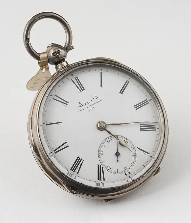
Chronometer watch in silver case by J.R. Arnold, Chas Frodsham, no.6530, 3/4 -plate movement, 1820-1833
Science Museum Group, London
Pocket Watches · 1850-1862; hallmarked 1862
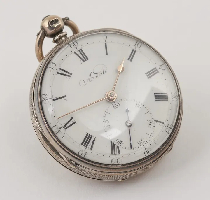
Cylinder watch in silver case by Jno. R. Arnold, London, no.3636, compensated curb, hall marked 1862
Science Museum Group, London
Pocket Watches · 1818–1819
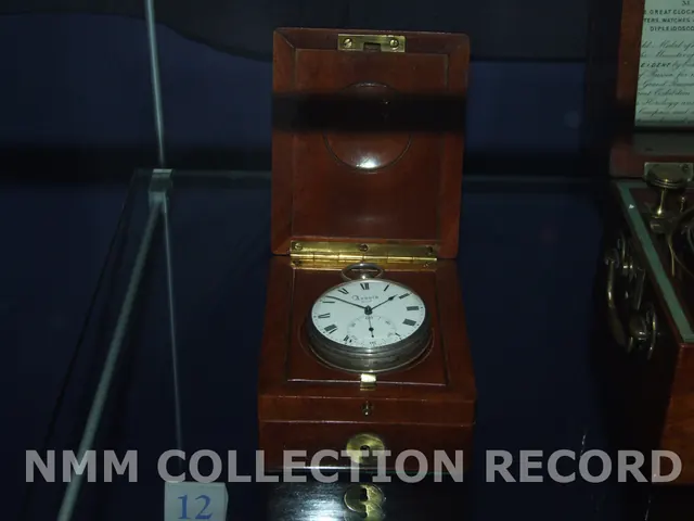
Pocket chronometer no. 2168 by John Roger Arnold
Royal Museums Greenwich
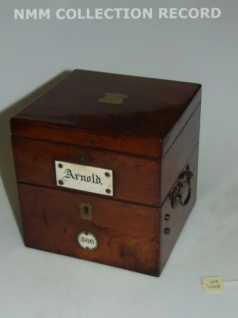
Instruments · c. 1843
Marine chronometer no. 366 by John Roger Arnold
Royal Museums Greenwich
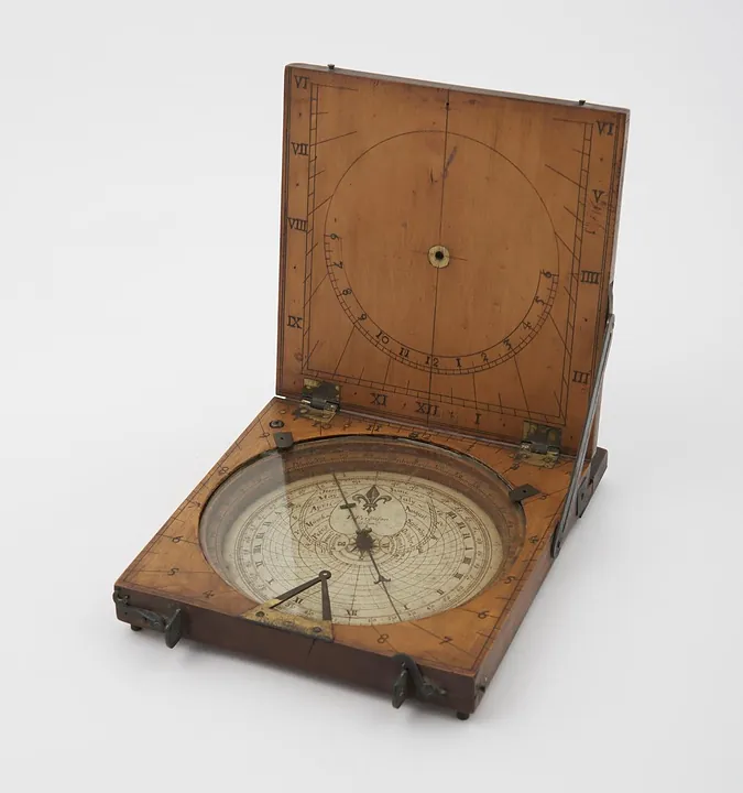
Instruments · 1731–1776
Azimuth compass sundial by James Ferguson, London, England, 1731–1776. Could also be used as a tablet sundial - string gnomon is missing (see note).
Science Museum Group, London
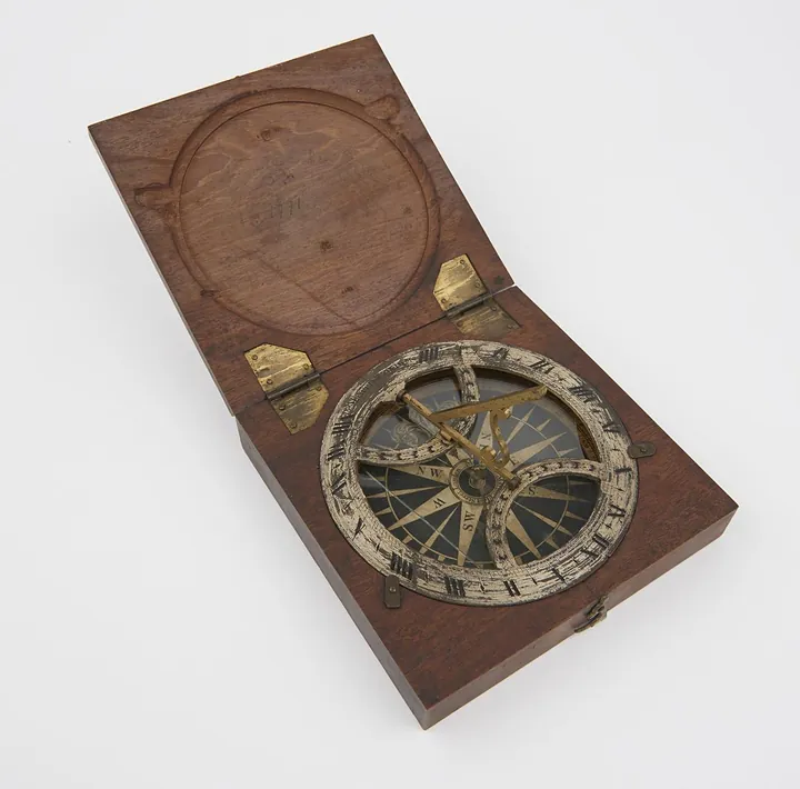
Instruments · 1738–1777
Azimuth sundial 4 3/8" diam, with folding gnomon fitted in mahogany case, made by B. Martin
Science Museum Group, London
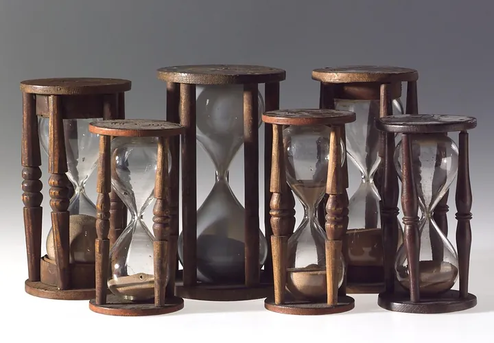
Instruments · 1750–1800
Single sand glass in four pillared wooden mount. 17 minutes. Horne Type B. Second half of the 18th century
Science Museum Group, London
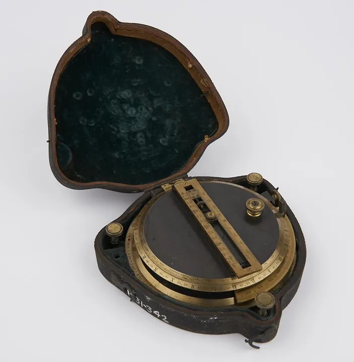
Instruments · 1751–1825
Sundial, by Troughton, in case. Invented and made by Troughton
Science Museum Group, London