
Instruments · Boxed marine chronometer
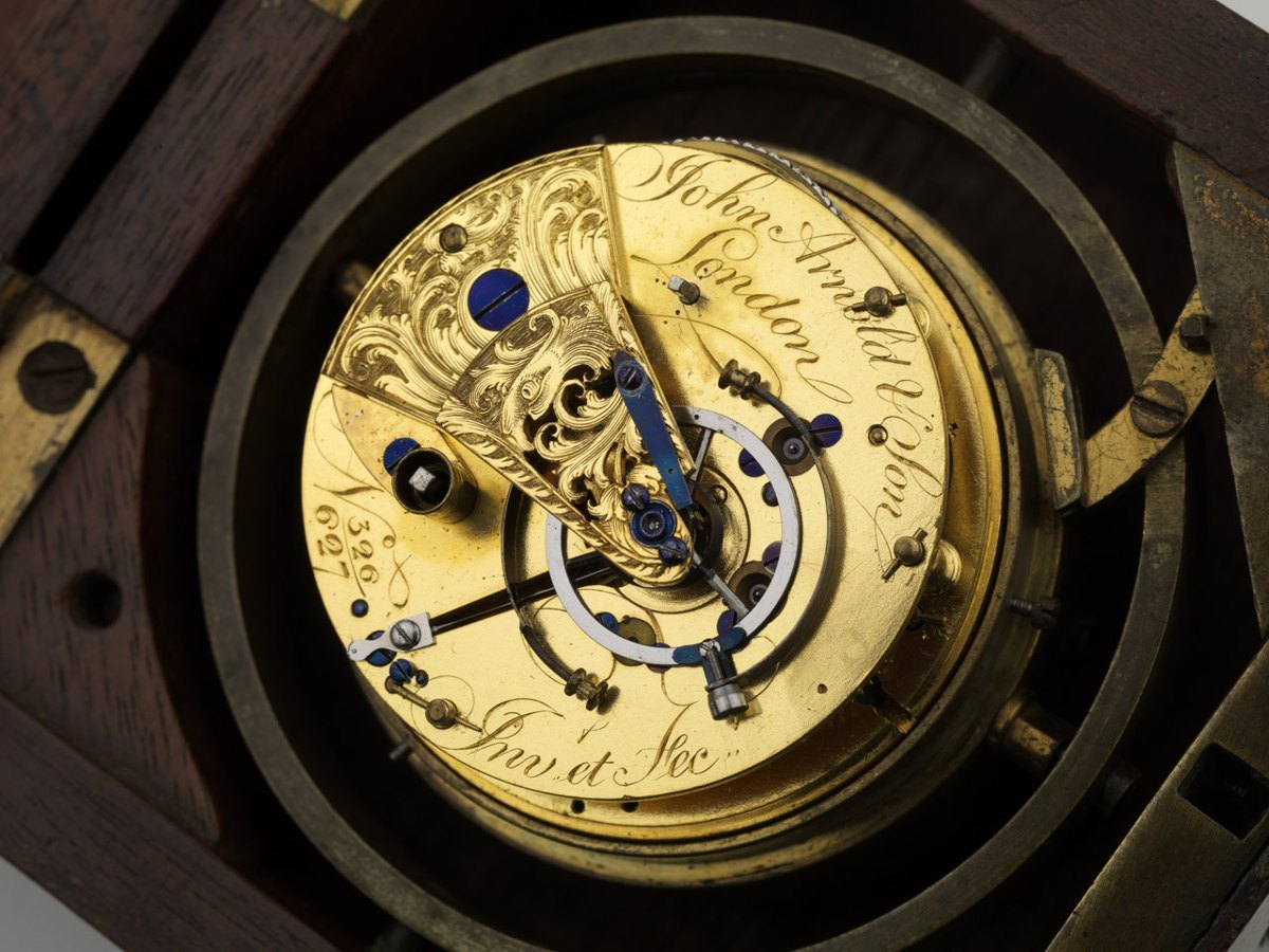
John Arnold & Son No. 326 Marine Chronometer
- Maker / attribution
- John Arnold & Son (source attribution)
- Date
- c. 1788-1810
- Historical period
- Precision & Scientific Horology (1750 – 1850)
- Country of origin
- United Kingdom
- Object type
- Boxed marine chronometer
- Dimensions
- 95 x 93 x 92 mm
- Holding institution
- National Maritime Museum, Greenwich, London, Rev. George Fisher Collection
- Accession / object no.
- john-arnold-son-no-326-marine-chronometer-d971bb60d3
- Credit line
- National Maritime Museum, Greenwich, London, Rev. George Fisher Collection
- Catalogue title (original)
- 326 | Royal Museums Greenwich (English)
View the source record ↗ (opens another website in a new tab)Suggest a correction
Record summary
Held and catalogued by National Maritime Museum, Greenwich, London, Rev. George Fisher Collection (object number john-arnold-son-no-326-marine-chronometer-d971bb60d3), this is a boxed marine chronometer attributed to John Arnold & Son, made in United Kingdom, dated c. 1788-1810. The Atlas places it in the Precision & Scientific Horology period (1750 – 1850) of its Instruments collection. Recorded dimensions: 95 x 93 x 92 mm. The record is illustrated with 1 photograph.
Assembled from the source record's structured fields. Dates and attributions are given as the source states them; where a field is missing the Atlas leaves it blank rather than estimating.
Catalogue description
Original object description
Produced in the United Kingdom circa 1788–1810, this boxed marine chronometer by John Arnold & Son began as a one-day pocket chronometer before being transferred around 1810 into a three-tier gimballed mahogany box measuring 95 x 93 x 92 mm with dovetailed corners. Inscribed in ink on the wooden box are notations citing the Reverend G. Fisher. Inside the gimbal bowl, a brass poise weight holds down a paper fragment inscribed "July 22nd 1836", written over an earlier, faded inscription of "1825". The gilded brass movement is built on a full-plate layout supported by four pillars and is driven by a fusee equipped with Harrison's maintaining power. Engraved on the potence plate are the makers' signature and the production reference "No. 326/627". Evidence of its initial casing remains in the form of a slanted lip atop the fusee pipe. Signs of subsequent modification include a plugged hole where the maintaining power spring originally sat, as well as burring under the balance cock foot indicative of repivoting or staff alterations. The escapement is an Arnold-type spring detent, which functions alongside a blued steel helical balance spring and an Arnold "OZ" balance; this balance features a three-armed steel hub united with bimetallic outer segments of blued steel and "Platina". A few unresolved manufacturing anomalies persist, including a minute hole through the outer edge of the steel center wheel, two unthreaded perforations close to the center pivot, and an errant drill depression that interrupts the matted gilding on the potence plate.
Inscriptions & marks
326/627
Historical context
Precision & Scientific Horology (1750 – 1850)
Harrison solves longitude; Mudge invents the lever; Breguet's Paris workshop defines the modern watch.
The longitude problem was solved by the marine chronometer and lunar distance methods; dividing engines made precision scales possible, and observatories set time by transit instruments.
Read the period in the timelineMore instruments from this periodEarlier: Early Modern Horology
Atlas type guide
Marine chronometers
A marine chronometer is a precision timekeeper carried at sea to find longitude: the navigator compares local noon, observed with a sextant, with the time at a reference meridian kept by the chronometer. Each hour of difference corresponds to fifteen degrees of longitude. John Harrison proved the method in the 1760s; Pierre Le Roy, Ferdinand Berthoud, John Arnold and Thomas Earnshaw then developed the detent escapement and the compensation balance that made chronometers practical to manufacture.
By the nineteenth century London, Liverpool, Le Locle and Glashütte supplied navies and merchant fleets. A typical box chronometer has a spring-detent escapement, a fusee to equalise mainspring torque, a bimetallic compensation balance with a helical balance spring, and is mounted in gimbals inside a wooden box so that it stays level.
What to look for
- Gimbals and a three-tier wooden box with a glazed inner lid.
- A power-reserve ('up and down') indicator on the dial, usually showing 56 hours on two-day instruments.
- Spring-detent escapement and a cylindrical (helical) balance spring visible through the movement.
- Admiralty or navy marks (broad arrow), and rating certificates from observatories.
- The maker's number on the dial and movement; many makers' registers survive, allowing dating.
Dating clues
- Earnshaw-type spring-detent chronometers became standard after about 1800.
- Auxiliary compensation devices on the balance appear from the mid-nineteenth century.
- Quartz and radio time signals ended routine use of mechanical chronometers in the 1970s and 1980s.
General guidance written by the Atlas editors about this kind of object. It is not a statement about this particular piece; for that, rely on the source record above and on physical examination.
Read next:Detent escapement
Related records
Instruments · 1795
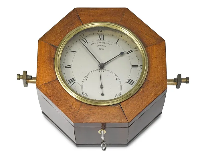
Marine chronometer by John Arnold & Son, England, 1795 (no. L2015-3486)
Science Museum Group, London
Instruments · 1795
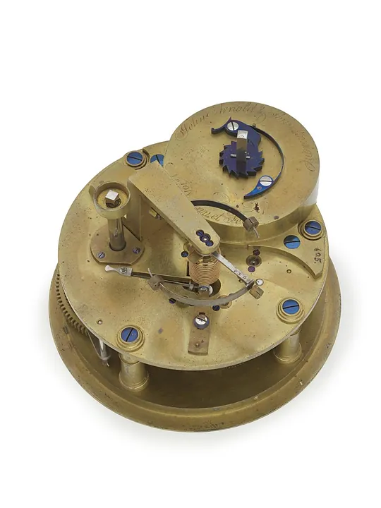
Marine chronometer by John Arnold & Son, England, 1795 (no. L2015-3487)
Science Museum Group, London
Pocket Watches · 1789
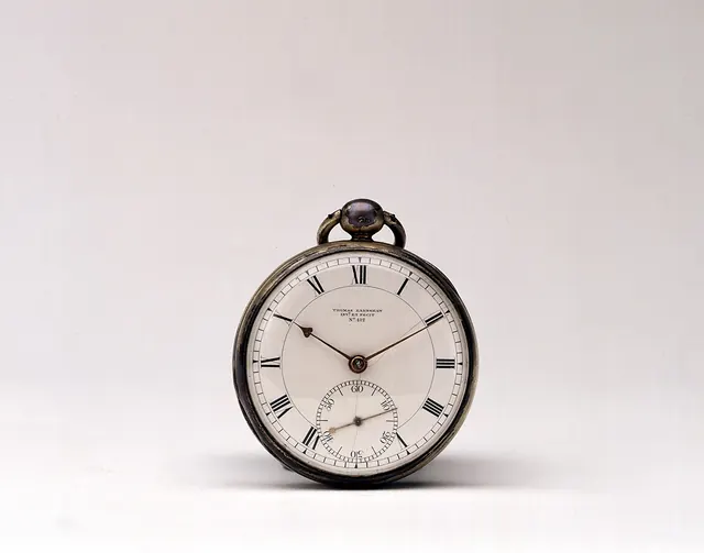
Pocket chronometer no. 412 by Thomas Earnshaw
Royal Museums Greenwich
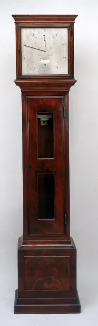
Clocks · c. 1789
Sidereal Angle Clock by John Arnold & Son
Royal Museums Greenwich
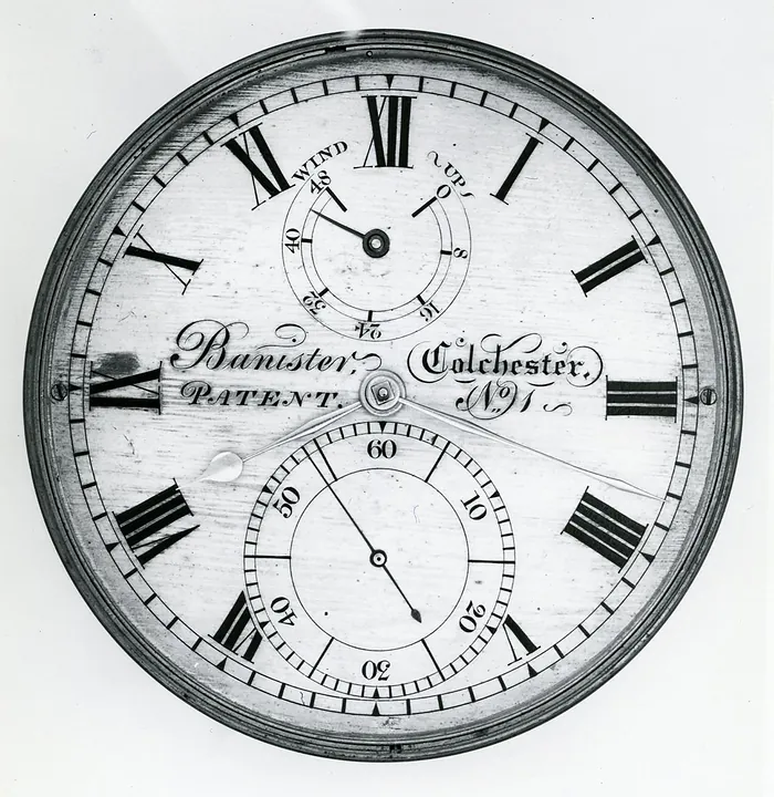
Instruments · 1830–1840
Joseph Banister Marine Chronometer 'Patent No. 1'
British Museum
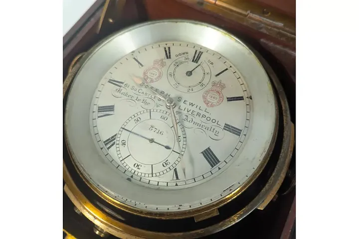
Instruments · 19th Century
Joseph Sewill two-day marine chronometer
Auctioneum Ltd - East Bristol & Bath
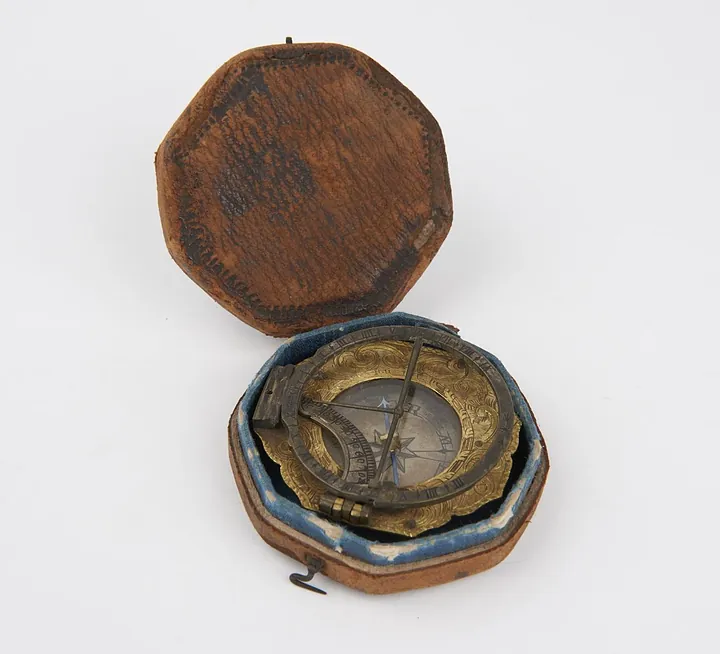
Instruments · 1726–1775
Universal equinoctial sundial of the Augsburg type, signed on the base "L T M" (Ludwig Theodatus Muller). In original case. German, mid 18th century. (B1670)
Science Museum Group, London
Instruments · 1731–1776
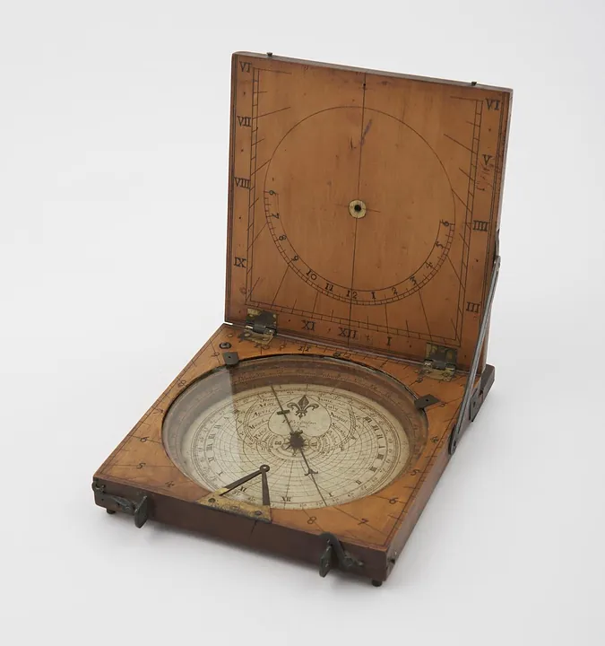
Azimuth compass sundial by James Ferguson, London, England, 1731–1776. Could also be used as a tablet sundial - string gnomon is missing (see note).
Science Museum Group, London