
Instruments · Aircraft-chronometer
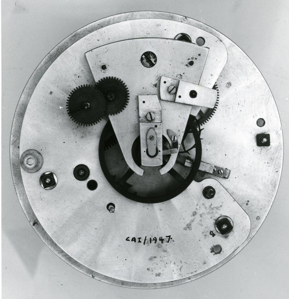
Aircraft chronometer by Leborne & Cie
- Maker / attribution
- Leborne & Cie (Movement made by)
- Date
- 1920-1925 (uncertain)
- Historical period
- Golden Age of Mechanical Watchmaking (1900 – 1945)
- Country of origin
- France
- Place
- France (?), Switzerland (?)
- Object type
- Aircraft-chronometer
- Materials / technique
- aluminium
- Holding institution
- British Museum
- Accession / object no.
- 1958,1006.1947
- Credit line
- British Museum, London
- Catalogue title (original)
- Aircraft chronometer; detent escapement; movement in turned aluminium canister; dial and hands missing (English)
View the source record ↗ (opens another website in a new tab)Suggest a correction
Record summary
Held and catalogued by British Museum (object number 1958,1006.1947), this is an aircraft-chronometer by Leborne & Cie, made in France (?), Switzerland (?), dated 1920-1925 (uncertain). The Atlas places it in the Golden Age of Mechanical Watchmaking period (1900 – 1945) of its Instruments collection. Materials and techniques recorded by the source: aluminium. The record is illustrated with 3 photographs.
Assembled from the source record's structured fields. Dates and attributions are given as the source states them; where a field is missing the Atlas leaves it blank rather than estimating.
Catalogue description
Description — British Museum
Aircraft chronometer; detent escapement; movement in turned aluminium canister; dial and hands missing.
Curator's comments — British Museum
Comment from Anthony G. Randall and Richard Good, Catalogue of Watches in the British Museum. Vol. VI (1990) Maker Unknown, Possibly the early 1920s Aircraft Chronometer (?) Box: The movement contained in a turned aluminium canister, in two halves, the lower half pushing into the upper half. The bottom is adjusted tight in a recess, it has a central brass bush held with three screws for the original winding arbor, now missing, and three equally spaced holes in the bottom for the fixing screws. There are two small holes in the side and a positioning peg for the middle plate of the frame which fits up against a narrow turned shoulder. There is a removable glazed top fitting on the upper half of the canister. Overall diam. 82.3 mm, h. 60.0 mm. Dial and hands: All missing. The dial was fixed with three feet and pins, probably without a dial plate. The indications for the hours and minutes and for the seconds were offset. There was also a reserve of going indicator. Movement: Most of the frame parts are punched 5. Plate under the dial diam. 71.6 mm; middle plate diam. 78.4 mm; lowest plate diam. 75.1 mm; overall frame h. 32.7 mm; lower frame h. 18.9 mm; upper frame h. 16.3 mm. Frame: Composed of three plates, in two tiers, each tier separated by three turned pillars, with retaining nuts and washers. The plates, bridges and cocks are made of aluminium, the pillars of steel. In the lower part of the frame, towards the bottom of the canister, are planted the fusee, barrel and their associated parts. In the section above are planted the going train and the escapement. The balance staff bearings are in the middle plate and in a cock on the back plate. There is a detachable barrel bridge with two retaining screws and two positioning pins. The mechanism is apparently intended to run dial up or approximately that position, as steel end plates are provided for all the going-train pivots on their lower ends. Fusee: Both the fusee cone and barrel are made of aluminium, English stop-work and Harrison's maintaining power are fitted. The maintaining ratchet wheel and great wheel are made of brass, the maintaining detent and spring are combined in a single steel piece. The fusee arbor is squared at the back, and carries a turned steel boss held with a pin through the arbor. A large brass wheel fits free to turn on a shoulder on the boss and is held on by a steel ratchet wheel with two screws going into the boss. Steel clicks and brass springs are fitted on the brass wheel. A pinion was once planted in the centre of the back plate with an arbor for winding passing through a brass bush in the bottom of the canister. This pinion must have been in permanent engagement with the winding wheel. Such an arrangement causes small variations in the torque output of the fusee. The mainspring barrel has a snap-on cover on both ends, a brass bearing bush is fitted into each cover. The steel barrel arbor has a large brass snailed boss. The very well finished and blued mainspring is signed 'Leborne et Cie 1869', it is attached by a hook and eye at both ends. Setting-up-work is fitted on the detachable barrel bridge. Going train: Conventional but well made train with brass wheels having a grained finish and square-bottom tooth form. The pinion leaves, the ends of the pinions and the arbors and pivots are well finished and polished. The pinion leaves are well cut with square bottoms. The centre arbor is planted between the back and front plates, the rest of train between the middle and front plates. The lower third and fourth pivots run in separate cocks on the underside of the middle plate, the fourth upper pivot in a cock on the side of the balance cock. Brass bushes are provided for all the pivots with steel endpieces for the lower bearings. Escapement: A novel type of detent escapement. The brass escape wheel is well and lightly made, and thinned on both sides so that only the tips of the teeth remain the full height. It is held by two small screws on a brass collet on its arbor. Both impulse and discharge rollers are of brass, their acting surfaces set with pieces of steel crudely fixed and badly finished. The impulse surface leans markedly towards a radial to the tip. The tip of the discharge roller unlocking pallet is almost on the same radius as the impulse roller. The detent is clamped on a fine wire of flat section, itself held in tension in a steel frame. The end of the steel frame is shaped round a steel boss in which is set the lower balance bearing, and held by two screws passing into the middle plate. The wire passes through a hole in the detent sufficiently large to admit two semicircular sections of brass as well, and there is a clamping screw set in the side of the detent. The locking stone is a half-round piece of polished steel, very rough, wedged in a hole by a piece of brass. The steel passing spring has a boss held by a screw on the underside of the detent, the free end of the spring presses against a pin at the nose of the detent. Banking for the detent is against an eccentric brass peg set in a hole in the edge of the steel frame under the detent, and secured by a brass nut. Balance: Plain brass four-armed balance riveted to a brass collet on the staff. The staff pivots are remarkably large in diameter, about 0.45 mm, and made like train pivots. The bearings are simply pierced brass with flat steel endpieces. Diam. of rim 28.1 mm, h. 2.1 mm. Balance spring: Grained steel helical spring of 5½open coils without teminal curves. There is apparently no thermal compensation and no means of bringing to time. The lower end of the spring is crudely bent in and pinned to a brass collet, the other end is pinned to a steel arm screwed on the balance cock. Reserve of going indication: On the fusee arbor is pinned an index piece similar to that for a Geneva stop-work. This indexes a brass wheel with nine slots on the arbor carrying the indicator hand. Going-train counts: Great wheel (fusee) 84 teeth, 8 turns of g.
Inscriptions & marks
signature; Leborne et Cie 1869 [mainspring]
Provenance
Previous owner/ex-collection:, Courtenay Adrian Ilbert, Previous owner/ex-collection:, Captain J H Jauncey; Donated by:, Gilbert Edgar; Acquired 1958
Historical context
Golden Age of Mechanical Watchmaking (1900 – 1945)
The wristwatch displaces the pocket watch; waterproof cases, self-winding and grand complications.
Timing instruments became electrical and specialised: industrial time recorders, sports timers and aviation instruments.
Read the period in the timelineMore instruments from this periodEarlier: Industrial Revolution
Atlas type guide
Marine chronometers
A marine chronometer is a precision timekeeper carried at sea to find longitude: the navigator compares local noon, observed with a sextant, with the time at a reference meridian kept by the chronometer. Each hour of difference corresponds to fifteen degrees of longitude. John Harrison proved the method in the 1760s; Pierre Le Roy, Ferdinand Berthoud, John Arnold and Thomas Earnshaw then developed the detent escapement and the compensation balance that made chronometers practical to manufacture.
By the nineteenth century London, Liverpool, Le Locle and Glashütte supplied navies and merchant fleets. A typical box chronometer has a spring-detent escapement, a fusee to equalise mainspring torque, a bimetallic compensation balance with a helical balance spring, and is mounted in gimbals inside a wooden box so that it stays level.
What to look for
- Gimbals and a three-tier wooden box with a glazed inner lid.
- A power-reserve ('up and down') indicator on the dial, usually showing 56 hours on two-day instruments.
- Spring-detent escapement and a cylindrical (helical) balance spring visible through the movement.
- Admiralty or navy marks (broad arrow), and rating certificates from observatories.
- The maker's number on the dial and movement; many makers' registers survive, allowing dating.
Dating clues
- Earnshaw-type spring-detent chronometers became standard after about 1800.
- Auxiliary compensation devices on the balance appear from the mid-nineteenth century.
- Quartz and radio time signals ended routine use of mechanical chronometers in the 1970s and 1980s.
General guidance written by the Atlas editors about this kind of object. It is not a statement about this particular piece; for that, rely on the source record above and on physical examination.
Read next:Detent escapement
Related records
Instruments · 1902
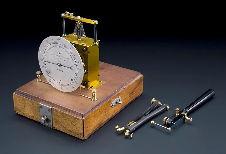
D'Arsonval electric chronometer, for measuring reflex reaction time, by Charles Verdin, Paris, 1902
Science Museum Group, London
Instruments · 1921–1940
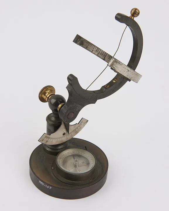
Universal equinoctial sundial. French, c.1930
Science Museum Group, London
Instruments · (Suspension ring and rule: 1939)
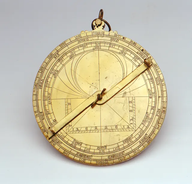
Astrolabe, France, (Suspension ring and rule: 1939)
Royal Museums Greenwich
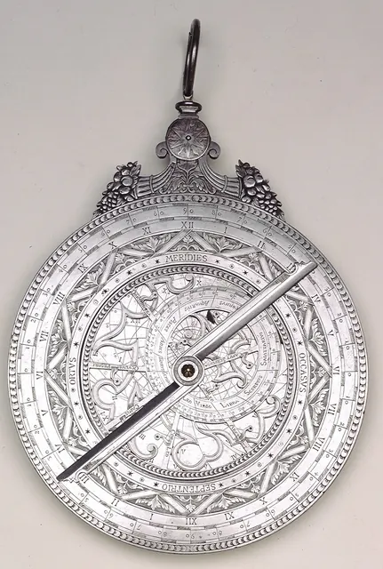
Instruments · 1900
Astrolabe, France, 1900
Royal Museums Greenwich
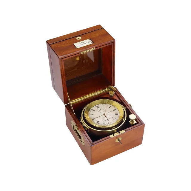
Instruments · c. 1915
L. Leroy & Cie marine chronometer, France Marine Chronometer, circa 1915
Antiquorum auction archive, Geneva
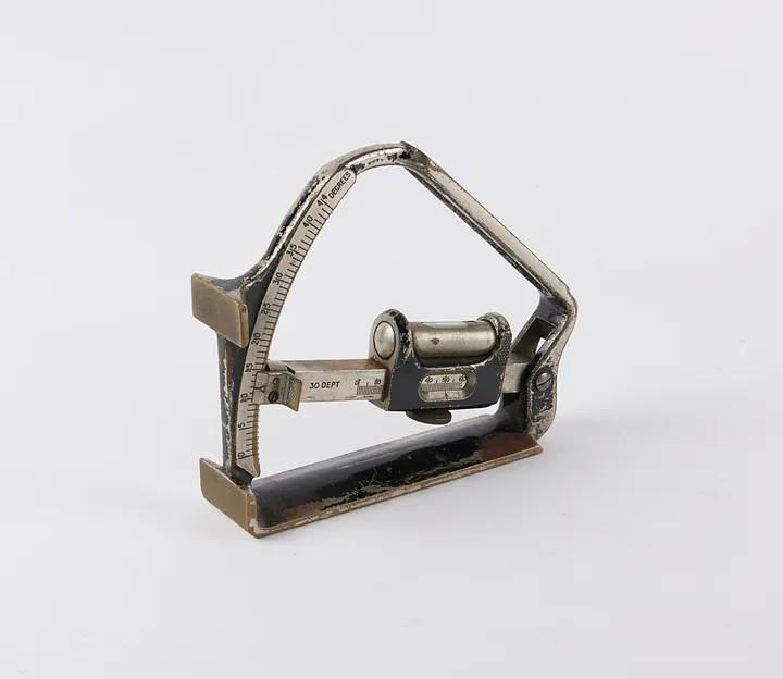
Instruments · Undated (20th century)
Field chronometer, Mark IV, no. 1621, by Taylor & Hobson Ltd.
Science Museum Group, London
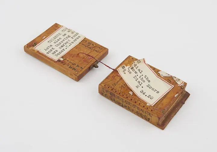
Instruments · 1880–1920
Compass and sundial, two hinged wooden blocks, compass needle set into one, covered with glass windows, painted with Chinese characters, Chinese, 1880–1920
Science Museum Group, London
Instruments · 1890–1930
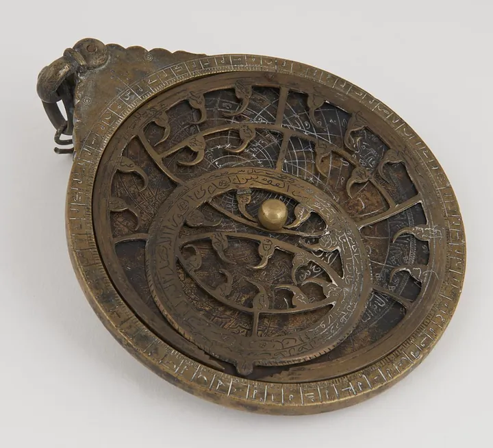
Decorative fake Islamic astrolabe with four plates and sightless alidade, pin missing.
Science Museum Group, London